Squeeze container liquid extrusion tool

a technology of extrusion tool and squeeze container, which is applied in the direction of flexible containers, portable flexible containers, packaging, etc., can solve the problems the the prior art caulk gun and hot melt glue gun cannot be used with liquid adhesive or a squeeze bottle, etc., to achieve the effect of increasing the pressure inside the squeeze bottl

Active Publication Date: 2017-05-09
BELANGER RICHARD A
View PDF118 Cites 9 Cited by
  • Summary
  • Abstract
  • Description
  • Claims
  • Application Information

AI Technical Summary

Benefits of technology

[0012]When a squeeze bottle of liquid is used, basic physical principles govern the function of the bottle and the liquid being dispensed. Generally, with a nearly-filled bottle fitted with a conical shaped nozzle that has an appropriately sized orifice, the bottle is stored in an upright vertical orientation with the cap or nozzle closed between uses. In this upright orientation, the liquid in the bottle flows to the bottom of the bottle due to gravity. The time needed for the liquid to level out after each use is a function of the inherent elastic property of the bottle, the viscosity of the liquid, and the ability of air evacuated during squeezing to re-enter the bottle through the nozzle. If the bottle is relatively firm, such as bottles made of HDPE, and the orifice is sufficiently large, the bottle returns to its original shape quickly and air re-enters the bottle almost instantly to expedite leveling of the liquid. On the other hand, if the bottle is made of a softer material, such as LDPE, and / or the orifice is very small (undersized), then the viscosity of the liquid causes it to remain in the bottle's orifice, therefore restricting air from re-entering the bottle and also slowing down leveling of the liquid. Similarly, a viscous liquid somewhat blocks re-entry of air into the bottle, leaving a temporary vacuum within the bottle.
[0014]When a volume of air is trapped behind the liquid and at equilibrium pressure with the outside air, squeezing the bottle reduces its volume, therefore increasing the pressure proportionally according to the well-known equation P1V1=P2V2. Of course, the pressure is highest when first squeezed and before any liquid exits the bottle. Then, as liquid exits the bottle, the volume of compressed air increases to take the place of the liquid expelled from the bottle, thus reducing pressure.
[0016]Further, in most squeeze bottle designs, the orifice is of a fixed diameter as determined by the manufacturer. In some cases it is a perfectly appropriate orifice size, but often it is not. Clearly, giving the user the ability to adjust the relationship between the liquid viscosity and the orifice of preference via a nozzle adjustment would improve the user's experience. While typical simple tips (known as “Yorker Tips” can be constructed with a tapered orifice area, it is up to the user to know ahead of time where along the taper to cut open the tip. Once the tip is cut “too big” there is no going back and the product will not be well controlled. Also, if the orifice is too small, the user is frustrated due to the time it takes for the bottle to take the necessary “breath” between squeezes to allow air to re-enter the bottle.

Problems solved by technology

The above-described caulk guns and hot-melt glue guns of the prior art all lack the ability to be used with glue or other flowable liquids contained in a squeeze bottle.
Hot met glue guns advance a stick of solid adhesive into a heated nozzle where it melts, but a hot melt glue gun could not be used with liquid adhesive or a squeeze bottle.
Also, unlike caulking tubes, which dispense caulk by a plunger pushing the caulk through the tube from the rear end, products contained in squeeze bottles are dispensed by a force applied to the sidewall or body of the squeeze bottle, therefore increasing the pressure inside the squeeze bottle and causing the product to flow through the nozzle or cap.
These condiment bottles generally offer a better overall experience than an old fashioned glass bottle, but they introduce other irritating issues to the process.
This type of solution is decidedly not appropriate for adhesives of a lower viscosity and most similar liquids.

Method used


Image

  • Squeeze container liquid extrusion tool
  • Squeeze container liquid extrusion tool
  • Squeeze container liquid extrusion tool

Examples


Embodiment Construction

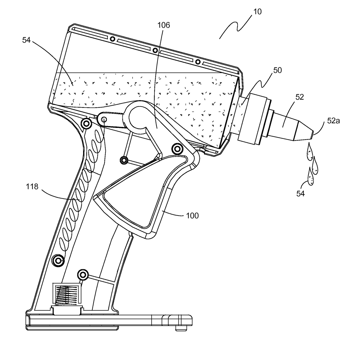
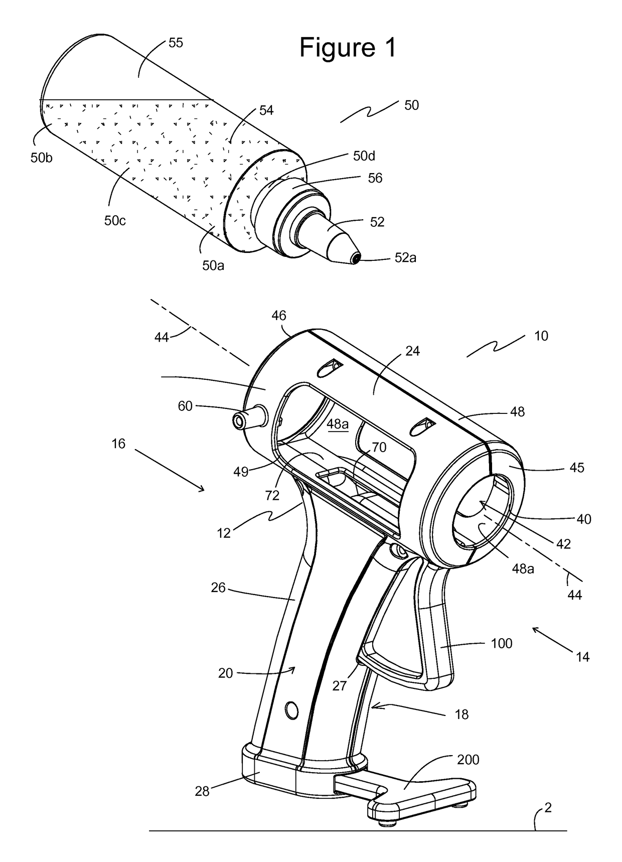
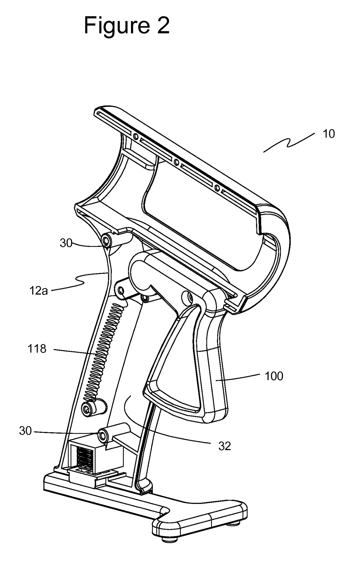
[0045]The preferred embodiments of the present invention are illustrated in FIGS. 1-11. FIG. 1 illustrates a front, top, and side perspective view of one embodiment of an extrusion tool 10 usable with a liquid or other flowable product 54 contained in a squeeze container 50. Squeeze container 50 may be, for example, a bottle, a tube, or other type of container. Extrusion tool 10 has a dispenser body 12 with a front portion 14, a rear portion 16, a first side portion 18, and a second side portion 20. Dispenser body 12 includes a container-receiving portion 24, a handle portion 26, and a base portion 28, where the handle portion 26 is connected to and extends between container-receiving portion 24 and base portion 28. A trigger 100 is operatively connected to dispenser body 12.

[0046]Container-receiving portion 24 has a front end 45 that defines a forward-facing aperture 40. Container-receiving portion 24 has a peripheral sidewall 48 that defines container well 42 extending longitudina...


PUM


Abstract

An extrusion tool includes a dispenser body having a handle portion, a container-receiving portion, and a base portion. The handle portion is connected to and extends between the container-receiving portion and the base portion. The container-receiving portion defines a forward-facing aperture and a container well extending along a container well axis, where the container well is constructed and arranged to receive and retain a squeeze container with a nozzle of the squeeze container extending through the forward-facing aperture. A trigger is operatively connected to the dispenser body and movable between a non-dispensing position and a dispensing position. The trigger has a finger portion and a contact lever portion that is oriented to move into and out of the container well when the finger portion is moved between the non-dispensing position and the dispensing position.

Description

BACKGROUND OF THE INVENTION[0001]1. Field of the Invention[0002]The present invention relates generally to applicators and extrusion devices for liquids, pastes and the like. More particularly, the present invention relates to an extrusion tool for use with adhesives and other liquids that are extruded from a squeeze container.[0003]2. Description of the Prior Art[0004]It has long been desirable to be able to dispense liquid products in a controlled manner, whether that product is glue, caulk, a lubricant, frosting, ketchup, paint, thixotropic resins, or any of a variety of similar liquids, gels, and flowable substances that could be extruded from a squeeze container.[0005]One prior art applicator is a caulking gun used with tubes of construction adhesive, caulk, and grease. The caulking gun has an elongated, hollow cylindrical frame that is sized to receive tubes of caulk and the like, where the tube has an extended tip and a piston that can be advanced into and along the tube to e...

Claims


Application Information

Patent Timeline
Patent Type & Authority Patents(United States)
IPC IPC(8): B65D37/00B05B11/04B05C17/005
CPCB05B11/048B05C17/00583
Inventor BELANGER, RICHARD A.
Owner BELANGER RICHARD A
Why Eureka
Try Eureka