
Display device compensating IR-drop of supply voltage

a display device and supply voltage technology, applied in the field of display devices, can solve the problems of degrading image quality and reducing the long range uniformity of the display device, and achieve the effects of reducing current, increasing the luminance of the row of pixels, and reducing the pulse width of the activation period

Active Publication Date: 2017-05-09
SAMSUNG DISPLAY CO LTD
View PDF12 Cites 0 Cited by
  • Summary
  • Abstract
  • Description
  • Claims
  • Application Information

AI Technical Summary

Benefits of technology

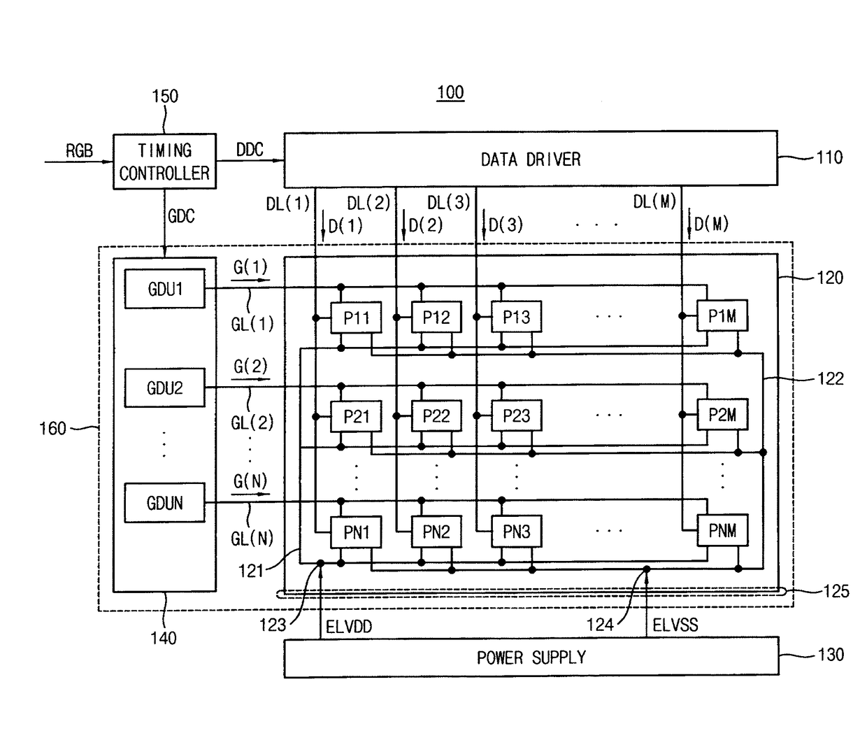
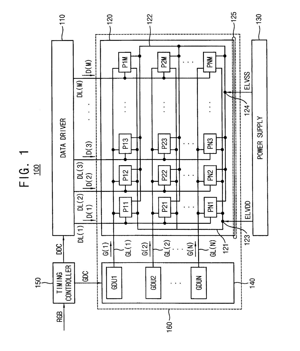
[0009]The first gate driver may decrease the current of the first gate signal when the first IR-drop increases. A pulse width of an activation period of the first gate signal may decrease and a luminance of the first row pixels may increase when the current of the first row pixels decreases. The first gate driver may increase the current of the first gate signal when the first IR-drop decreases. A pulse with of an activation period of the first gate signal may increase and a luminance of the first row pixels may decrease when the current of the first row pixels increases.
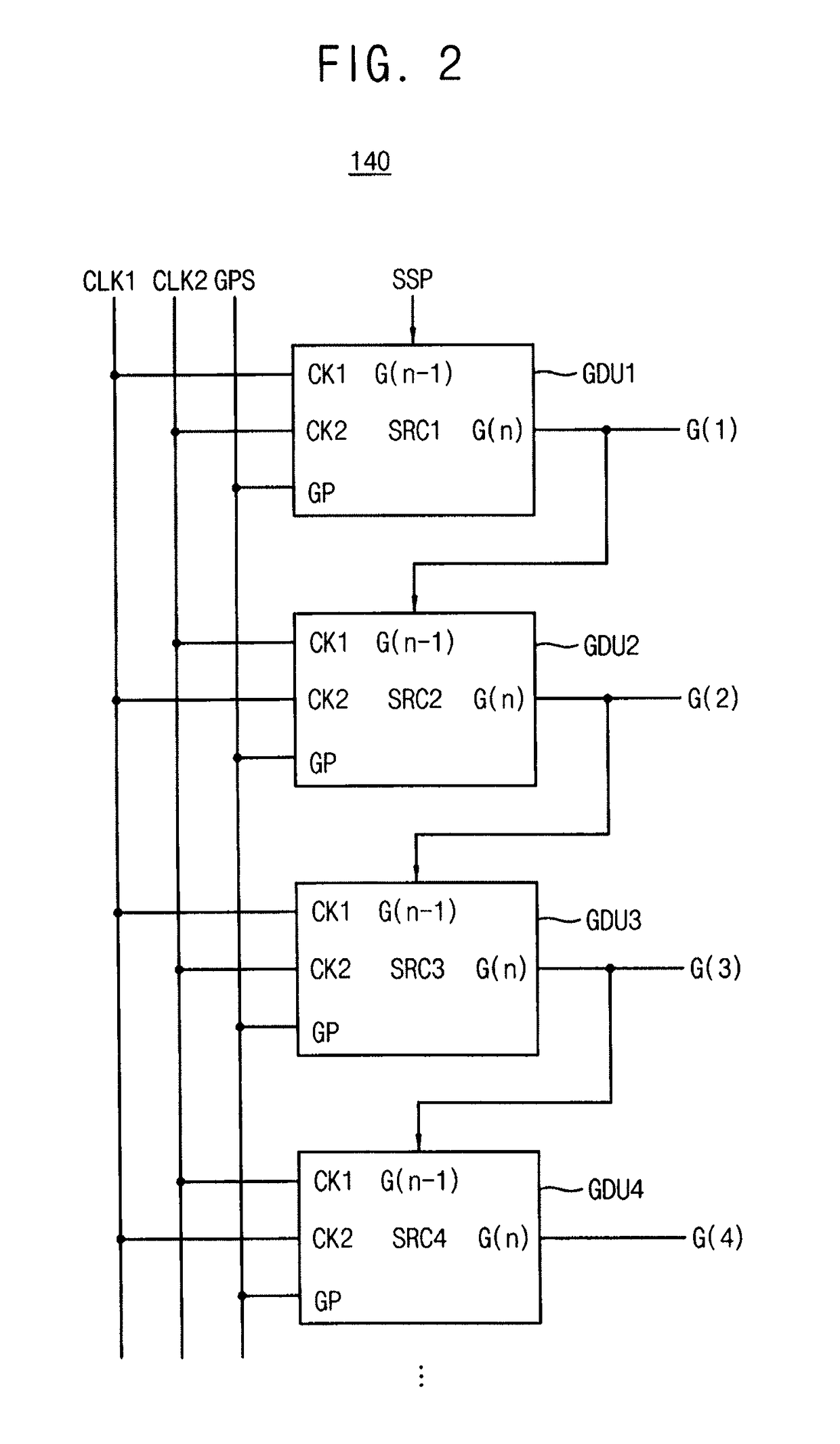
[0016]The gate driver may include an output transistor to generate the gate signal, and wherein the current of the gate signal is based on a ratio of a width and a length of the output transistor. The gate driver may decrease the current of the first gate signal when the IR-drop increases. A pulse width of an activation period of the gate signal may decrease and a luminance of the row of pixels may increase when the current of the first row of pixels decreases. The gate driver may increase the current of the gate signal when the IR-drop decreases.

Problems solved by technology

A voltage drop (IR-drop) occurs on the distribution lines to cause degradation in image quality.
Also, a lower supply voltage and data signals having lower voltages may affect the amount of current flowing through the driving transistors of the pixels, and also may degrade long range uniformity of the display device.

Method used


Image

  • Display device compensating IR-drop of supply voltage
  • Display device compensating IR-drop of supply voltage
  • Display device compensating IR-drop of supply voltage

Examples


Embodiment Construction

[0028]Example embodiments are described more fully hereinafter with reference to the accompanying drawings; however, they may be embodied in different forms and should not be construed as limited to the embodiments set forth herein. Rather, these embodiments are provided so that this disclosure will be thorough and complete, and will fully convey exemplary implementations to those skilled in the art. In the drawings, the dimensions of layers and regions may be exaggerated for clarity of illustration. Like reference numerals refer to like elements throughout.

[0029]It will be understood that when an element is referred to as being “connected” or “coupled” to another element, it can be directly connected or coupled to the other element or intervening elements may be present. In contrast, when an element is referred to as being “directly connected” or “directly coupled” to another element, there are no intervening elements present. Other words used to describe the relationship between e...


PUM


Abstract

A gate driver circuit includes a gate driver coupled to a gate line. The gate driver generates a gate signal for input to a plurality of pixels and controls a current of the gate signal based on an IR-drop of a supply voltage supplied to the pixels through a supply voltage distribution line. The gate driver decreases the current of the gate signal when the IR-drop increases, and increases the current of the first gate signal when the IR-drop decreases. A pulse width of an activation period of the gate signal decreases and luminance of the pixels increases when the current of the first row pixels decreases.

Description

CROSS-REFERENCE TO RELATED APPLICATION[0001]Korean Patent Application No. 10-2014-0147786, filed on Oct. 28, 2014, and entitled, “Display Device Compensating Ir-Drop Of Supply Voltage,” is incorporated by reference herein in its entirety.BACKGROUND[0002]1. Field[0003]One or more embodiments described herein relate to a display device that compensates IR-drop of a supply voltage.[0004]2. Description of the Related Art[0005]An organic light-emitting display uses pixels which emit light from organic light emitting diodes (OLEDs). Each diode emits light based on a recombination of electrons and holes in an active layer. Displays of this type offer numerous advantages including fast response speed and low power consumption.[0006]Each pixel includes a driving transistor that provides current to an OLED, which causes the OLED to emit light with a grayscale level based on image data. In order to emit light, a supply voltage and data signals are provided via distribution lines in the display...

Claims


Application Information

Patent Timeline
Patent Type & Authority Patents(United States)
IPC IPC(8): G06F3/038G09G3/3266G09G3/3233
CPCG09G3/3266G09G3/3233G09G2320/0223G09G2330/02
Inventor BYUN, MIN-WOO
Owner SAMSUNG DISPLAY CO LTD
Learn More