Motor drive controller and control method of motor drive controller
a technology of motor drive controller and control method, which is applied in the direction of electronic commutation motor control, motor/generator/converter stopper, and control of dynamo-electric converters. it can solve the problems of narrow target rotation speed, small number of signal patterns which can be used to set the target speed, and inability to easily configure the command signal input to the motor speed controller. it can easily change the setting of the target rotation speed, and achieve the effect of simple input o
- Summary
- Abstract
- Description
- Claims
- Application Information
AI Technical Summary
Benefits of technology
Problems solved by technology
Method used
Image
Examples
first embodiment
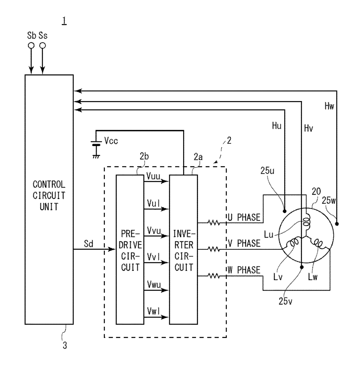
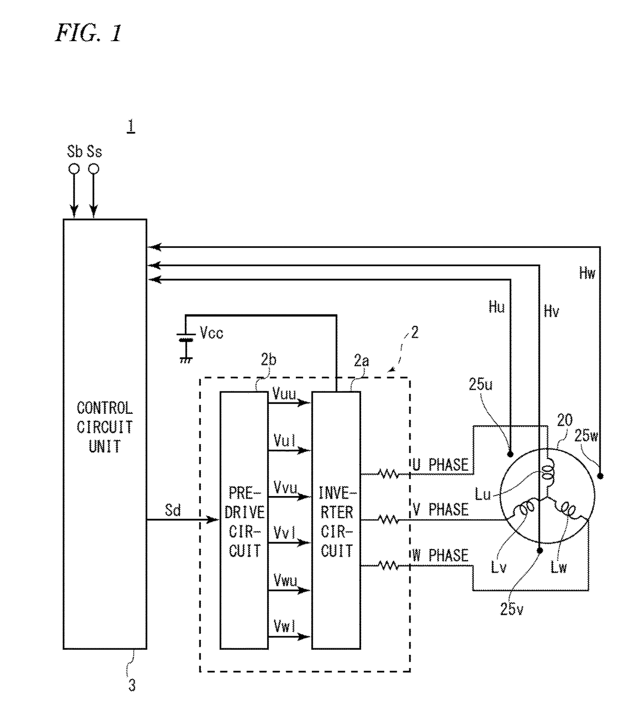
[0024]FIG. 1 is a diagram illustrating a circuit configuration of a motor drive controller 1 according to a first embodiment of the invention.
[0025]As illustrated in FIG. 1, the motor drive controller 1 is configured to drive a brushless motor 20 (hereinafter, simply referred to as a motor 20), for example, by sine wave drive. In this embodiment, the motor 20 is, for example, a three-phase brushless motor. The motor drive controller 1 rotates the motor 20 by outputting a sine-wave drive signal to the motor 20 to cause a sinusoidal drive current to periodically flow in armature coils Lu, Lv, and Lw of the motor 20.
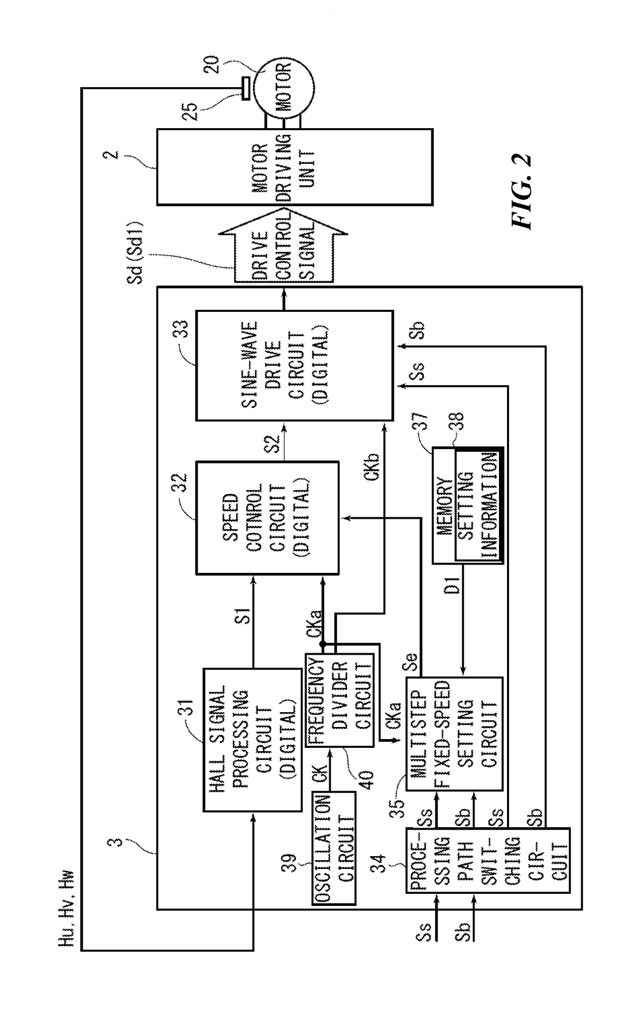
[0026]The motor drive controller 1 is provided with a motor drive unit 2 including an inverter circuit 2a and a pre-drive circuit 2b and a control circuit unit 3. The components of the motor drive controller 1 illustrated in FIG. 1 may be only a part of the motor drive controller 1, and the motor drive controller 1 may further be provided with other components in addition t...
second embodiment
[0106]A basic configuration of a motor drive controller according to a second embodiment may be the same as that of the first embodiment and description for the similar parts and operation thereof will not be repeated. The second embodiment is different from the first embodiment, in that a signal path through which a rotation speed command signal is input from the outside in addition to the step command signal is formed.
[0107]FIG. 7 is a diagram illustrating a circuit configuration of a motor drive controller 101 according to the second embodiment of the invention.
[0108]As illustrated in FIG. 7, in the motor drive controller 101, a control circuit unit 103 having a slightly different configuration is formed instead of the control circuit unit 3 of the first embodiment. In the control circuit unit 103, a signal path through which a rotation speed command signal Sc is input is formed in addition to the signal path through which the start signal Ss and the brake signal Sb (or the step ...
PUM
 Abstract
Description
Claims
Application Information
 - R&D
- Intellectual Property
- Life Sciences
- Materials
- Tech Scout
- Unparalleled Data Quality
- Higher Quality Content
- 60% Fewer Hallucinations
Browse by: Latest US Patents, China's latest patents, Technical Efficacy Thesaurus, Application Domain, Technology Topic, Popular Technical Reports.
© 2025 PatSnap. All rights reserved.Legal|Privacy policy|Modern Slavery Act Transparency Statement|Sitemap|About US| Contact US: help@patsnap.com


