
Cloud based drive monitoring solution

a monitoring solution and cloud technology, applied in the field of remote monitoring, can solve the problems of affecting production, affecting and proving costly to entities employing industrial devices, and ensuring the stability and integrity of industrial devices can prove dangerous to those relying on industrial equipment, etc., to facilitate the facilitate the effect of remote monitoring of industrial devices

Active Publication Date: 2017-05-09
ROCKWELL AUTOMATION TECH
View PDF18 Cites 11 Cited by
  • Summary
  • Abstract
  • Description
  • Claims
  • Application Information

AI Technical Summary

Benefits of technology

The present patent describes a cloud-based remote monitoring system for industrial facilities. The system includes a cloud agent located at the facility, which collects data on the state of the industrial devices, and sends it to a remote cloud platform. The platform processes the data to facilitate remote monitoring of the devices. The technical effect of this system is that it provides a flexible and efficient way to monitor industrial devices remotely without interrupting the collecting and sending process.

Problems solved by technology

Failure to maintain the stability and integrity of industrial devices can affect production and prove costly to entities employing the industrial devices.
Further, maintaining the stability and integrity of industrial devices can prove dangerous to those relying upon industrial equipment to, for example, generate power or pump gas to generate heat.
However, industrial equipment may not always be easily accessed.
Further, those with the technical know how to identify anomalies and / or patterns indicative of failure may not be on-site.
Sending maintenance and / or repair personnel to a field installation is costly.
Previous remote monitoring implementations involved customized software and infrastructure configurations, which are cumbersome to maintain and update.
Further, on-premise data collection required by such remote monitoring systems consumes large amounts of data storage.
Moreover, since potentially sensitive plant data is to be transmitted to a remote viewer, secure data transmission channels are required.

Method used


Image

  • Cloud based drive monitoring solution
  • Cloud based drive monitoring solution
  • Cloud based drive monitoring solution

Examples


Embodiment Construction

[0024]Various aspects of this disclosure are now described with reference to the drawings, wherein like reference numerals are used to refer to like elements throughout. In the following description, for purposes of explanation, numerous specific details are set forth in order to provide a thorough understanding of one or more aspects. It should be understood, however, that certain aspects of this disclosure may be practiced without these specific details, or with other methods, components, materials, etc. In other instances, well-known structures and devices are shown in block diagram form to facilitate describing one or more aspects.

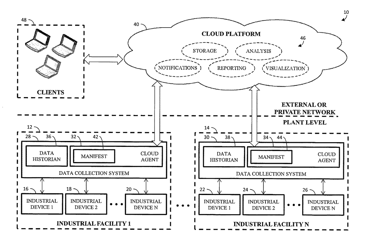
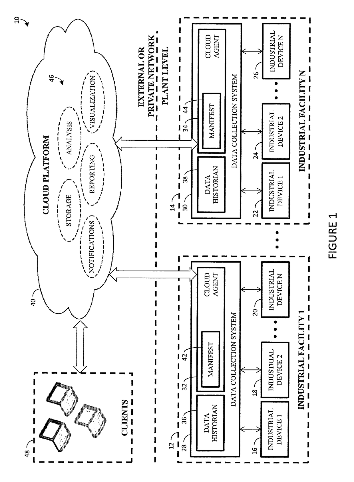
[0025]With reference to FIG. 1, a cloud-based remote monitoring system 10 including one or more industrial facilities 12, 14 is provided. Each industrial facility 12, 14 corresponds to an industrial enterprise. For example, a first industrial facility can correspond to a first industrial enterprise, and a second industrial facility can correspond to a ...


PUM


Abstract

A cloud-based remote monitoring system and method monitor an industrial facility. The industrial facility includes one or more industrial devices. A cloud agent located at the industrial facility is configured to, by at least one processor, collect data indicative of a past and / or a present state of the industrial devices according a manifest specific to the industrial facility. The cloud agent is further configured to send the collected data to a remote cloud platform according to the manifest dynamically reconfigure the cloud agent without interrupting the collecting and the sending. The cloud platform processes the sent data to facilitate remote monitoring of the industrial devices.

Description

[0001]This application claims the benefit of U.S. Patent Application No. 61 / 721,859, filed Nov. 2, 2012.BACKGROUND[0002]The present exemplary embodiments relate to remote monitoring. They find particular application in conjunction with industrial devices, such as the POWERFLEX 7000, and will be described with particular reference thereto. However, it is to be appreciated that the present exemplary embodiments are also amenable to other like applications.[0003]Maintaining stability and integrity of industrial devices is a high priority. Industrial devices include, for example, motor drives, such as the POWERFLEX 7000. Motor drives are used to generate and provide alternating current (AC) output power to a motor. Failure to maintain the stability and integrity of industrial devices can affect production and prove costly to entities employing the industrial devices. Further, maintaining the stability and integrity of industrial devices can prove dangerous to those relying upon industri...

Claims


Application Information

Patent Timeline
Patent Type & Authority Patents(United States)
IPC IPC(8): G06F15/177G05B19/048H04L12/26G05B23/02H04L12/24
CPCH04L43/04G05B19/048G05B23/0297G05B2219/13H04L41/046H04L43/0817G05B2223/06G06F16/21Y02P90/80G05B19/4185G05B2219/31151H04L41/0813
Inventor ASENJO, JUAN L.MATURANA, FRANCISCO
Owner ROCKWELL AUTOMATION TECH
Learn More