
Utility tunnel inspection robot and utility tunnel inspection system

A technology of inspection robots and comprehensive pipe corridors, applied in the field of robots, can solve problems such as poor ventilation, narrow space, and poor emergency response, and achieve extensive industrial value, improve safety, and use well.

Inactive Publication Date: 2018-01-16
四川君逸数码科技股份有限公司
View PDF8 Cites 12 Cited by
  • Summary
  • Abstract
  • Description
  • Claims
  • Application Information

AI Technical Summary

Problems solved by technology

[0005] 1. Underground inspection by personnel, the space is narrow, the ventilation is poor, the visual operation environment is poor, and the flammable, explosive and toxic gases pose a great threat to the life of the inspection personnel;
[0006] 2. The location of the underground inspection of personnel cannot be accurately reflected. Once personal danger occurs, timely and accurate rescue cannot be carried out;
[0007] 3. For abnormal equipment failures and dangerous scenarios in the pipe gallery, it is impossible to go down the well manually, and it is impossible to obtain the abnormal situation underground in the first time, and it is impossible to accurately provide decision support data, and it is impossible to deal with abnormal failures and dangerous control in a timely manner. The degree of emergency response Difference;
[0008] 4. Personnel inspections are costly, and the number of daily inspections and maintenance is small, so it is impossible to realize 24-hour circular dynamic inspections; each inspection requires high manpower, material resources, and vehicle resources (requires the cooperation of multiple people, Use a crane to lift the cover of the pipe gallery, and someone needs to communicate through the walkie-talkie on the ground and underground) to effectively monitor potential safety failures and risks in the pipe gallery

Method used


Image

  • Utility tunnel inspection robot and utility tunnel inspection system
  • Utility tunnel inspection robot and utility tunnel inspection system
  • Utility tunnel inspection robot and utility tunnel inspection system

Examples


Embodiment Construction

[0047] In order to facilitate the understanding of the present invention, the integrated utility gallery inspection robot and the integrated utility gallery inspection system will be described more comprehensively below with reference to the relevant drawings. The preferred embodiment of the comprehensive utility gallery inspection robot and the comprehensive utility gallery inspection system is given in the accompanying drawings. However, the integrated utility gallery inspection robot and the integrated utility gallery inspection system can be implemented in many different forms, and are not limited to the embodiments described herein. On the contrary, the purpose of providing these embodiments is to make the disclosed contents of the comprehensive utility gallery inspection robot and the comprehensive utility gallery inspection system more thorough and comprehensive.

[0048] Hereinafter, the terms "comprising" or "may include" that may be used in various embodiments of the...


PUM


Abstract

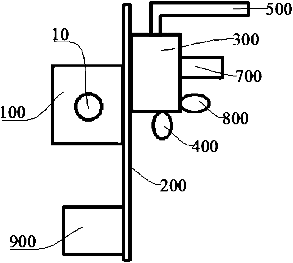
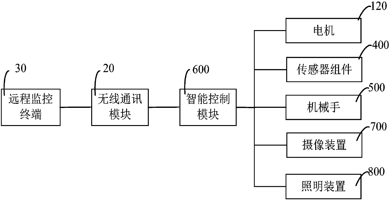
The invention discloses a utility tunnel inspection robot and a utility tunnel inspection system. The inspection robot comprises a moving module, which is slidingly arranged on a guide rail, a movingcarrier connected to the moving module, an inspection robot body, which is slidingly arranged on the moving carrier, a sensor assembly arranged on the inspection robot body, a mechanical arm arrangedon the inspection robot body, and an intelligent control module for controlling the inspection robot. The sensor assembly and the mechanical arm are both connected to the intelligent control module. The inspection robot can adapt with complicated conditions of utility tunnels, is capable of rapidly, comprehensively, circularly, and dynamically inspecting utility tunnels in 24 hours, and greatly improves the utility tunnel safety and inspection efficiency.

Description

technical field [0001] The invention relates to the technical field of robots, in particular to an inspection robot for an integrated pipe gallery and an inspection system for an integrated pipe gallery. Background technique [0002] In order to implement unified planning, design, construction and maintenance, the municipal public facilities built underground in the city and used for municipal public pipeline laying become comprehensive pipe corridors. The comprehensive pipe corridor has increasingly become an important part of the power grid, water network and other systems in cities or densely populated areas, and its reliable and stable operation is the basis for ensuring urban functions. [0003] The existing patrol inspection and monitoring of integrated utility tunnels mainly rely on manual inspection. Manual inspection is mainly through people going underground to identify the relevant equipment, environment, etc. in the pipe gallery through human eyes in the pipe ga...

Claims


Application Information

Patent Timeline
IPC IPC(8): G07C3/00G01D21/02H04N7/18G08C17/02
Inventor 张志锐曾立军蒲泽新
Owner 四川君逸数码科技股份有限公司
Learn More