Pedestrian protection system for a vehicle

a technology for protecting systems and vehicles, applied in vehicle safety belts, bumpers, vehicle components, etc., can solve problems such as the change of electromagnetic field in the cavity, and achieve the effect of reducing the space requiremen

Active Publication Date: 2017-05-16
VOLKSWAGEN AG
View PDF30 Cites 2 Cited by
  • Summary
  • Abstract
  • Description
  • Claims
  • Application Information

AI Technical Summary

Benefits of technology

[0011]It is therefore an object of the present invention to provide a reduction of the space requirement of the above-described pedestrian protection system.
[0013]According to an embodiment of the invention, the deformation element is thus deformed upon collision with a collision object, for example, a pedestrian. By the deformation of the deformation element the kinetic energy is converted to deformation energy in order to lessen the accident consequences for the pedestrian and the passengers. An effective lessening of the accident consequences is expediently achieved by a suitable selection of the material (material combinations may also be considered) and suitable dimensioning. The cavity is also changed in its spatial form (shape and / or volume) by the deformation of the deformation element. This leads to a change in the electromagnetic field in the cavity. An electromagnetic field is also understood to be an electric field or a magnetic field. Said change is detected by the at least one sensor and the resulting signals are analyzed by the control unit. A particular advantage of the pedestrian protection system of the invention is that the foam which takes up a great deal of space can be omitted without reducing the effectiveness of the pedestrian protection. This is useful especially in smaller vehicles in which sufficient space is otherwise not available to install an effective pedestrian protection system. In addition, a smaller space requirement also has advantages for design and costs. Thus, the overhang, for instance, can be shortened, which brings with it not only lower material costs but also more free space for the design.
[0015]In an embodiment, the deformation element can be made as a metallic cage. The use of metallic materials, for example, sheet metal, makes it possible, on the one hand, to use inductive sensors for detecting the change in the electromagnetic field alternatively or in addition to capacitive sensors. On the other hand, a metallic cage has a high energy absorbing capacity and flexibility in the case of an impact. It has proven especially advantageous to configure the metallic cage with slit-shaped openings.
[0016]An especially reliable installation of the deformation element is achieved with the deformation element attached to the crossmember. A large opening in the deformation element allows for the deformation element to be expediently attached to the crossmember so that the edge of the large opening lies against the crossmember.
[0017]The risk of injury and possible accident consequences for the pedestrian in an impact with the vehicle can be reduced, if the control unit is designed to trigger the pedestrian protection functions of the vehicle as a function of the signals of the at least one sensor. Advantageously a function of raising the hood of the vehicle, a so-called active hood or engine hood, is provided as the pedestrian protection function to be triggered. For example, a windshield airbag is also conceivable as a further pedestrian protection function to be triggered.

Problems solved by technology

This leads to a change in the electromagnetic field in the cavity.

Method used


Image

  • Pedestrian protection system for a vehicle
  • Pedestrian protection system for a vehicle
  • Pedestrian protection system for a vehicle

Examples


Embodiment Construction

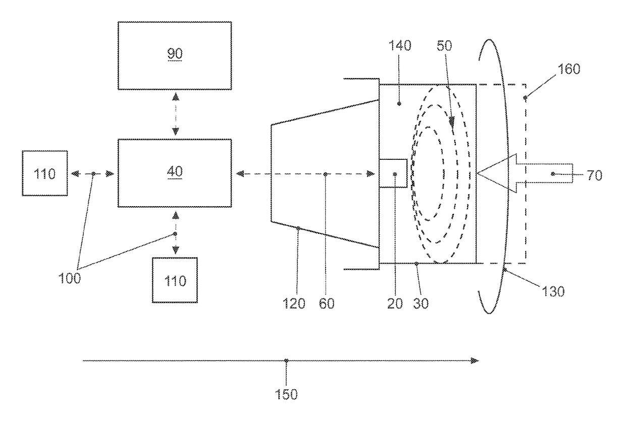
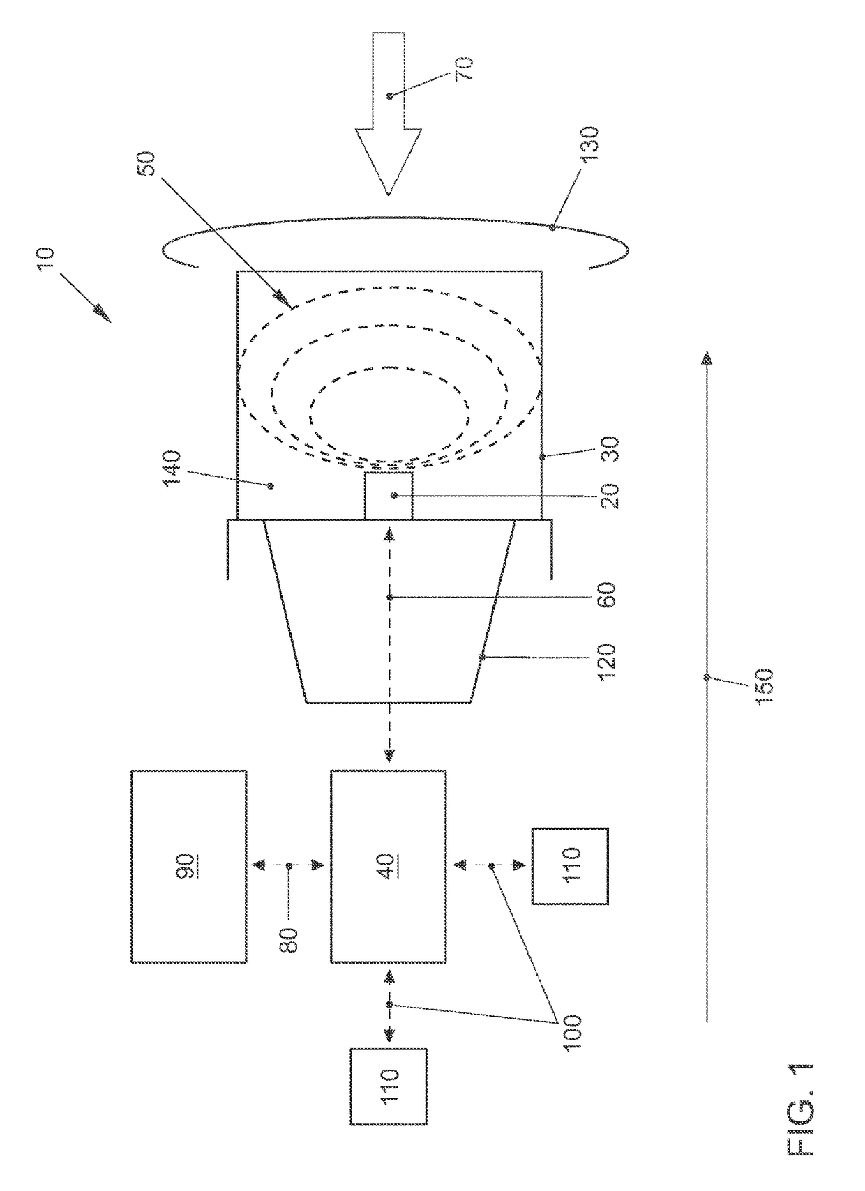
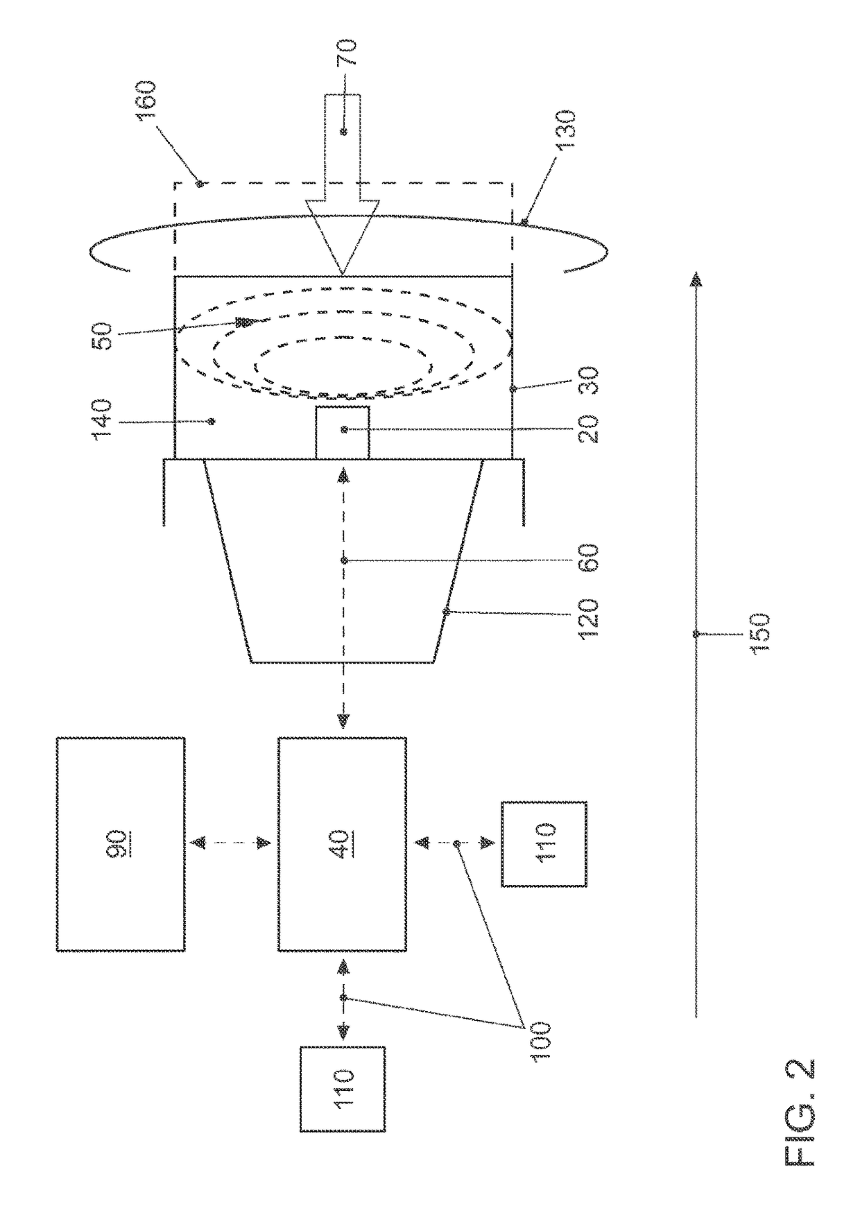
[0024]FIG. 1 shows a pedestrian protection system 10 of the invention. Pedestrian protection system 10 has a capacitive sensor 20, a deformation element 30, and a control unit 40.

[0025]Sensor 20 monitors an electric field 50 generated by sensor 20. Electric field 50 does not change during accident-free operation of the vehicle (not shown in greater detail) in which pedestrian protection system 10 is installed. Capacitive sensor 20 is connected to control unit 40 via a bidirectional data line 60, for example, a CAN bus (CAN: Controller Area Network). Capacitive sensor 20 transmits its signals via data line 60 to the capacitive sensor. Control unit 40 is capable of transmitting control signals to sensor 20 via data line 60. Such control signals can serve the following purposes: activating sensor 20; deactivating sensor 20; diagnosing sensor 20; and changing electrical field 50 in order to adjust the field strength to changed ambient conditions.

[0026]Control unit 40 analyzes the receiv...


PUM


Abstract

A pedestrian protection system for a vehicle, having at least one impact-detecting sensor and a deformable element that are arranged between a cross-member and a bumper cover of the vehicle, and a control unit that analyzes the signals of the at least one sensor. In order to reduce the amount of space required, the deformable element is designed as a deformable member that it has a cavity in which the at least one sensor is arranged and detects changes in an electromagnetic field in the cavity.

Description

[0001]This nonprovisional application is a continuation of International Application No. PCT / EP2013 / 058004, which was filed on Apr. 17, 2013, and which claims priority to German Patent Application No. DE 10 2012 013 327.8, which was filed in Germany on Jul. 6, 2012, and which are both herein incorporated by reference.BACKGROUND OF THE INVENTION[0002]Field of the Invention[0003]The present invention relates to a pedestrian protection system for a vehicle having at least one impact-detecting sensor and a deformation element, which are arranged between a crossmember and a bumper cover of the vehicle, and having a control unit which analyzes the signals of the at least one sensor.[0004]Description of the Background Art[0005]A pedestrian protection system is disclosed in DE 10 2004 009 301 A1, which corresponds to US2007179693, and in DE 103 60 138 A1.[0006]In the embodiment disclosed in DE 10 2004 009 301 A1, a bumper cover is arranged in front of a foam and a crossmember of the vehicle...

Claims


Application Information

Patent Timeline
Patent Type & Authority Patents(United States)
IPC IPC(8): B60R22/00B60R21/36B60R21/34B60R21/38B60R19/48B60R21/0136B60R21/01B60R21/00
CPCB60R21/34B60R19/483B60R21/01B60R21/0136B60R21/36B60R21/38B60R2021/0004B60R2021/01013B60R2021/01252
Inventor GAAS, THORSTENLESCHKE, ANDREHACKENBERG, ULRICHPLOEGER, RICARDOSTRUTZ, TORSTEN
Owner VOLKSWAGEN AG
Why Eureka
Try Eureka