

System and method for improved simultaneous localization and mapping
a simultaneous localization and mapping technology, applied in the field of simultaneous localization and mapping, can solve the problems of grossly distorting the map, compounding errors, and excessive computation costs for nearly all but very powerful computers, and achieve the effect of reducing the number of features
- Summary
- Abstract
- Description
- Claims
- Application Information
AI Technical Summary
Benefits of technology
Problems solved by technology
Method used
Image

Examples
Embodiment Construction
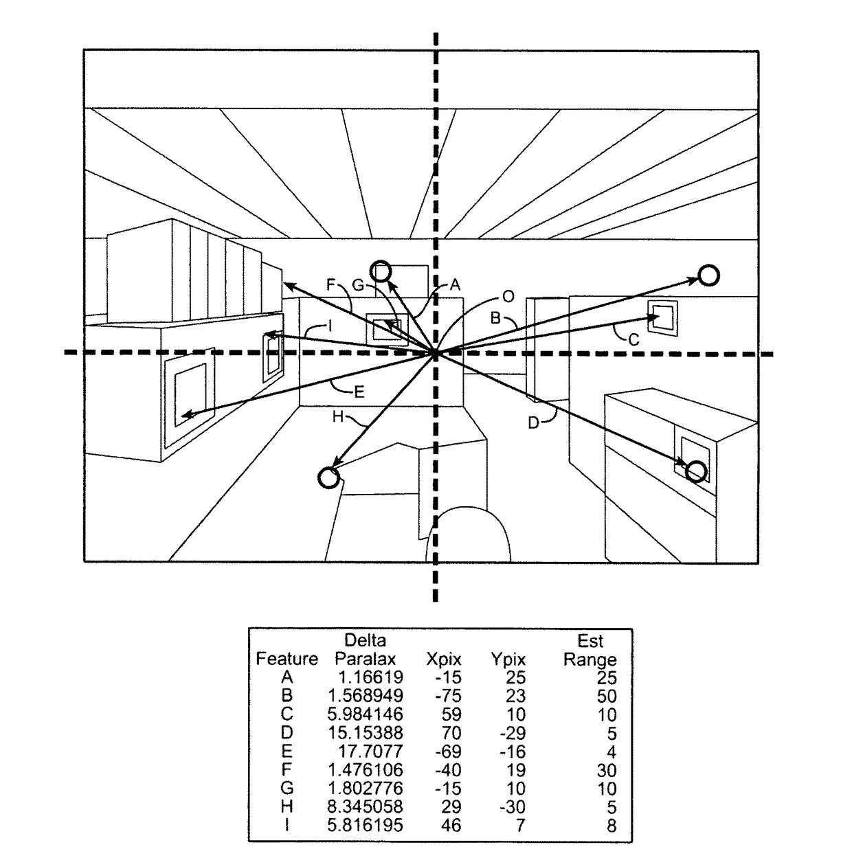
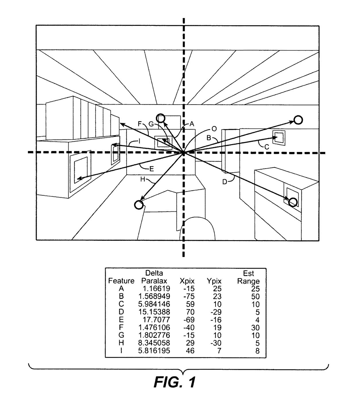
[0029]FIG. 1 is a schematic of a sample feature selection in a SLAM environment. A central location or origin O, which can be in a SLAM calculation the location of mechanical, inertial, optical, acoustic or magnetic sensors and any associated 10 device(s), forms the center of the vision field, from which the delta parallax and angular distance of each physical landmark A, B, C, D, E, F, G, H, I from the central location vision field may be computed from the data collected by the SLAM sensors. The landmarks constitute features (or feature data) within the system that the system references and relates to, and include any features stored in memory within the system. The delta parallax may be a parallax between any two points, with the first point being a reference point to the second point, and any other point features, such as features A, B, C, D, E, F, G, H, I in FIG. 1. The parallax can be described as some angle plus or minus some angle-error. The angular distance likewise may be d...
PUM
 Abstract
Description
Claims
Application Information