
Hydraulic freewheel for an internal combustion engine with variable compression ratio

a hydraulic adjustment and internal combustion engine technology, applied in the direction of shafts, bearings, rotary bearings, etc., can solve the problems of large oil volume flow, weakening the bearing load capacity, and damage to components, and achieve the effect of reducing the throttling effect and small temperature dependen

Active Publication Date: 2017-06-13
FEV
View PDF5 Cites 8 Cited by
  • Summary
  • Abstract
  • Description
  • Claims
  • Application Information

AI Technical Summary

Benefits of technology

[0026]A characteristic of the hydraulic resistance can be, for example, described as follows: compared to a friction brake, for instance, a limitation of the pivoting speed of the eccentric by means of a hydraulic resistance already has the advantage of a rate-proportional braking effect. As a resistance, both a throttle and an orifice, as well as a combination of both can be used. The use of an orifice has the advantage that the relationship between the flow rate and the pressure difference has only a very small temperature dependence. Thus, the influence of the oil temperature on the adjustment time is also little. In a system realized, the flow behavior of the path from the pressure-loaded support cylinder to the crankcase or the expanding support cylinder will be situated between the behavior of a pure throttle flow and a pure orifice flow. A temperature dependence that is as low as possible can be achieved by reducing the throttling effect in all lines to and from the resistance, as far as possible, i.e. by providing correspondingly large line cross-sections. Thereby, resistance realized as a pure orifice is by far the dominant resistance.

Problems solved by technology

Experimental studies have shown that an adjustment from one end position to the other, for example, of an eccentric in the small connecting rod eyelet, can be realized within one working cycle, however, the components are damaged when a mechanical end stop is reached.
A VCR system of such design has the following disadvantages:a. during the adjustment, a large oil volume flow is required to fill the momentarily expanding support cylinder.
Specifically the grooves in the connecting rod bearing weaken the bearing load capacity.
Conversely, this means that the adjustment rate must be strongly limited in order to still be able to reliably supply the expanding support cylinder even with a small supply line system.b. Upstream of the non-return valve, the supply pressure of the connecting rod bearing prevails.

Method used


Image

  • Hydraulic freewheel for an internal combustion engine with variable compression ratio
  • Hydraulic freewheel for an internal combustion engine with variable compression ratio
  • Hydraulic freewheel for an internal combustion engine with variable compression ratio

Examples


Embodiment Construction

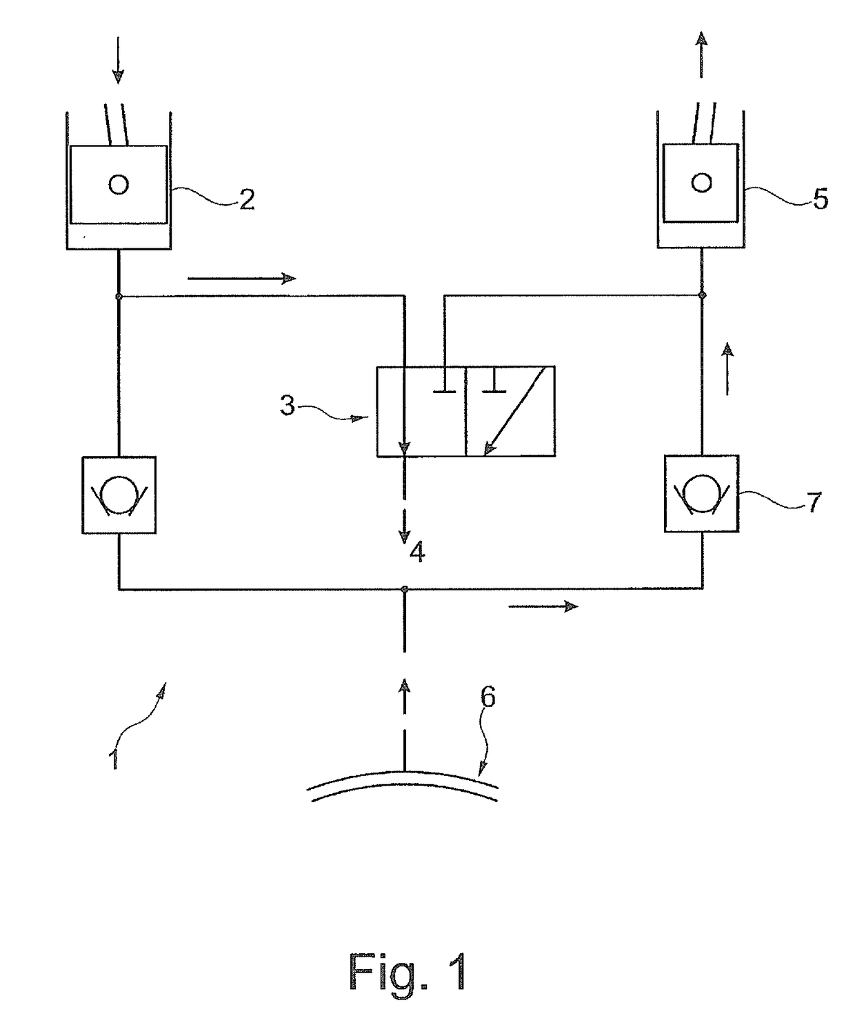
[0095]FIG. 1 shows a hydraulic freewheel with a 3 / 2-way valve, as known from DE 10 2005 055 199. In the switching position 1 illustrated, the left support piston 2 may plunge. The oil displaced from this cylinder flows via the valve 3 into the crankcase 4. The expanding support cylinder 5 draws fresh oil from the supply groove 6 via the non-return valve 7. In this arrangement, the following states exist:

a) the eccentric can rotate clockwise

b) the eccentric can rotate in a counterclockwise direction

[0096]Thus, two stable compression stages exist, so that the system may be referred to as a 2-stage VCR system. However, in operation, the VCR system may show problems as described in more detail above.

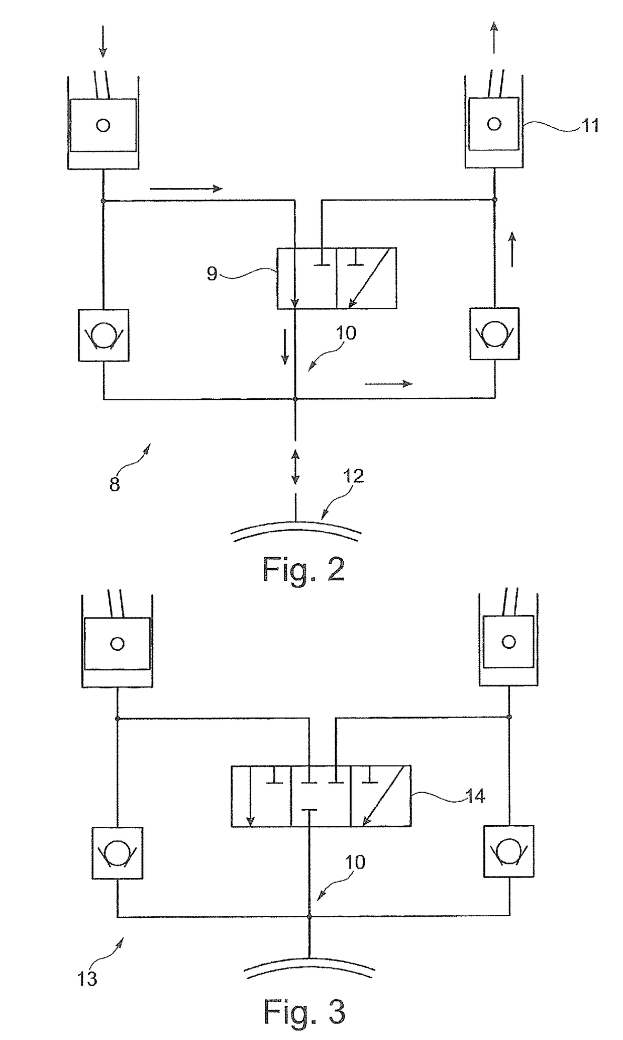
[0097]FIG. 2 shows a hydraulic diagram 8 with a 3 / 2-way valve 9 and an internal oil transfer 10. The quantity of oil displaced is used to fill the expanding support cylinder 11. Depending on the diameter ratio of the support cylinder and the lever ratios, either more oil is displaced than is...


PUM


Abstract

A reciprocating-piston internal combustion engine having a hydraulic adjustment mechanism which is assigned to a connecting rod and which comprises at least one eccentric, for adjusting at least one variable compression ratio in at least one cylinder of the reciprocating-piston internal combustion engine by means of a change in an effective length of a connecting rod. Also proposed is a method for changing the effective length of a connecting rod.

Description

CROSS-REFERENCE TO RELATED APPLICATIONS[0001]This application is the U.S. national phase of PCT / EP2013 / 002255 filed Jul. 30, 2013, which claims priority of German Patent Application 10 2012 014 916.6 filed Jul. 30, 2012, and German Patent Application 10 2012 020 999.1 filed Oct. 26, 2012, the entire contents of which are incorporated herein by reference.FIELD OF THE INVENTION[0002]The present invention relates to a reciprocating-piston internal combustion engine with a hydraulic adjusting mechanism assigned to a connecting rod and comprising at least one eccentric arranged in a connecting rod bearing eyelet or a piston pin bearing eyelet of a connecting rod for adjusting at least one variable compression ratio of the combustion in at least one cylinder of the reciprocating-piston internal combustion engine by changing the effective length of the connecting rod by means of the adjusting mechanism.BACKGROUND OF THE INVENTION[0003]Various technical approaches for a variable compression...

Claims


Application Information

Patent Timeline
Patent Type & Authority Patents(United States)
IPC IPC(8): F02B75/04F02B75/26F16C23/10F16C7/06
CPCF02B75/045F16C7/06F16C23/10F16C2360/22
Inventor WITTEK, KARSTEN
Owner FEV
Learn More