Terminating impedance circuit for an electroabsorption modulator

a technology of terminating impedance circuit and modulator, which is applied in the direction of optics, instruments, light guides, etc., can solve the problems of frequent inability to integrate the eml and terminating impedance circuit, local concentrated heating of the circuit, etc., and achieves favorable effect of heat dissipation of the distributed terminating resistor, and is cheaper and more reliabl

Active Publication Date: 2017-06-13
FRAUNHOFER GESELLSCHAFT ZUR FOERDERUNG DER ANGEWANDTEN FORSCHUNG EV
View PDF3 Cites 1 Cited by
  • Summary
  • Abstract
  • Description
  • Claims
  • Application Information

AI Technical Summary

Benefits of technology

[0014]In some embodiments, the technological realization of the terminating impedance circuit may be directly on a modulator chip on which the electroabsorption modulator is also implemented with a laser (or laser source). In this case, the terminating impedance circuit is integrated monolithically with the electroabsorption modulator. This monolithic realization may be cheaper and more reliable than a hybrid structure that may be used in addition to the modulator chip.
[0015]Furthermore, the monolithic solution may, at least in some embodiments, be more precise and more broad-banded than an external hybrid setup. In some embodiments, its elongate shape may effect heat dissipation of the distributed terminating resistor favorably.

Problems solved by technology

When realizing a radio-frequency circuit comprising discrete electric components, typically the impedance values of a circuit may be only of a limited precision, except the circuit is tuned to the desired impedance value in a manual and complicated manner.
This may result in a local concentrated heating of the circuit, i.e. in direct proximity to the discrete ohmic resistor.
However, without such thermal decoupling, such an integration of the EML and the terminating impedance circuit would frequently not be practical.

Method used


Image

  • Terminating impedance circuit for an electroabsorption modulator
  • Terminating impedance circuit for an electroabsorption modulator
  • Terminating impedance circuit for an electroabsorption modulator

Examples


Embodiment Construction

[0028]In the following description of embodiments of the invention, same elements or elements of equal effect in the figures are provided with same reference numerals, so that the description thereof in the different embodiments is mutually exchangeable.

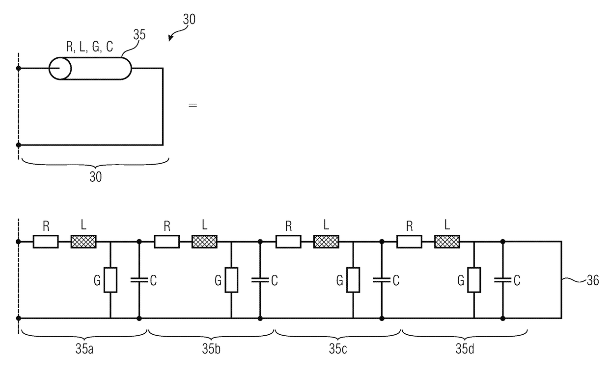
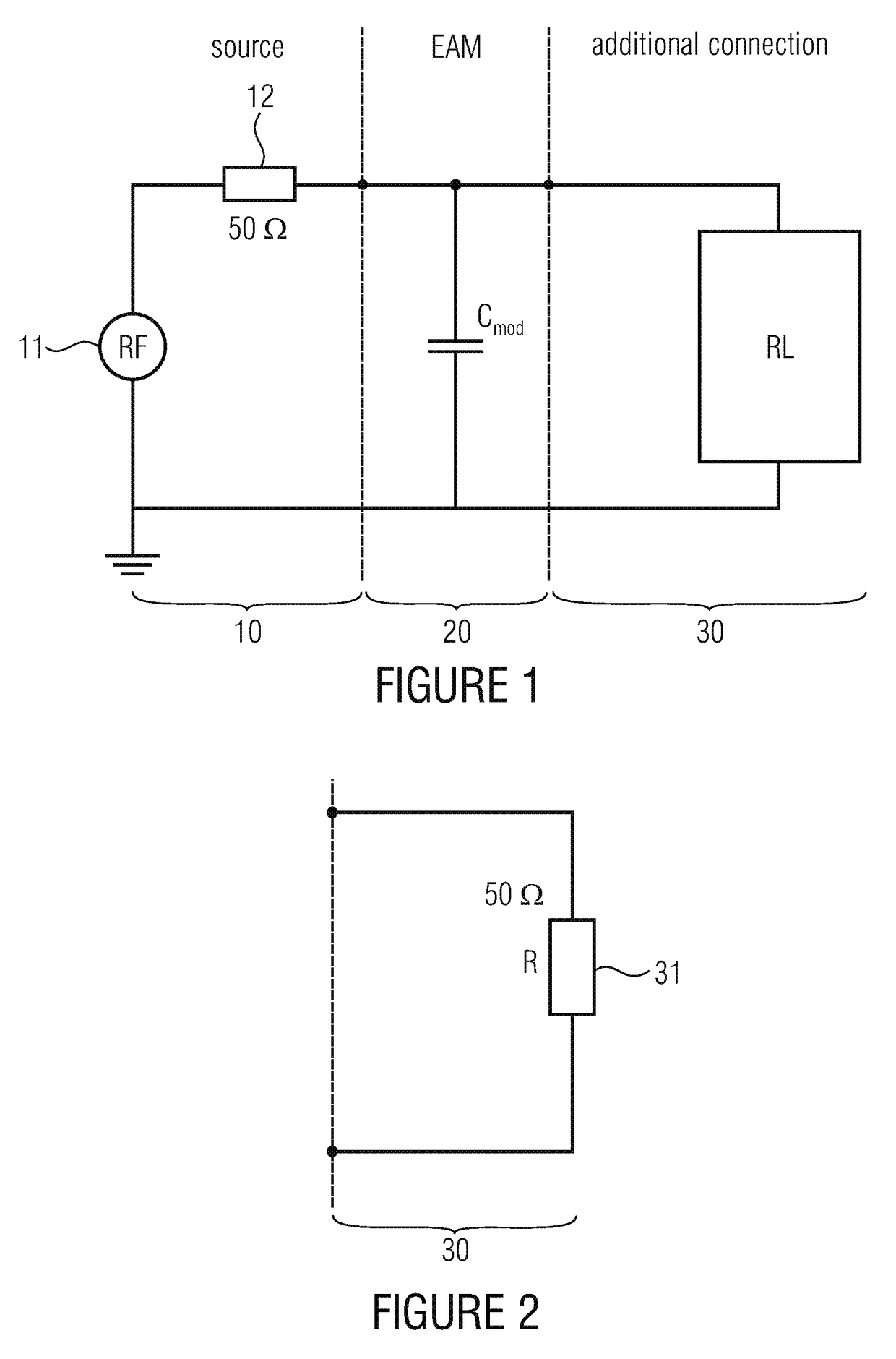
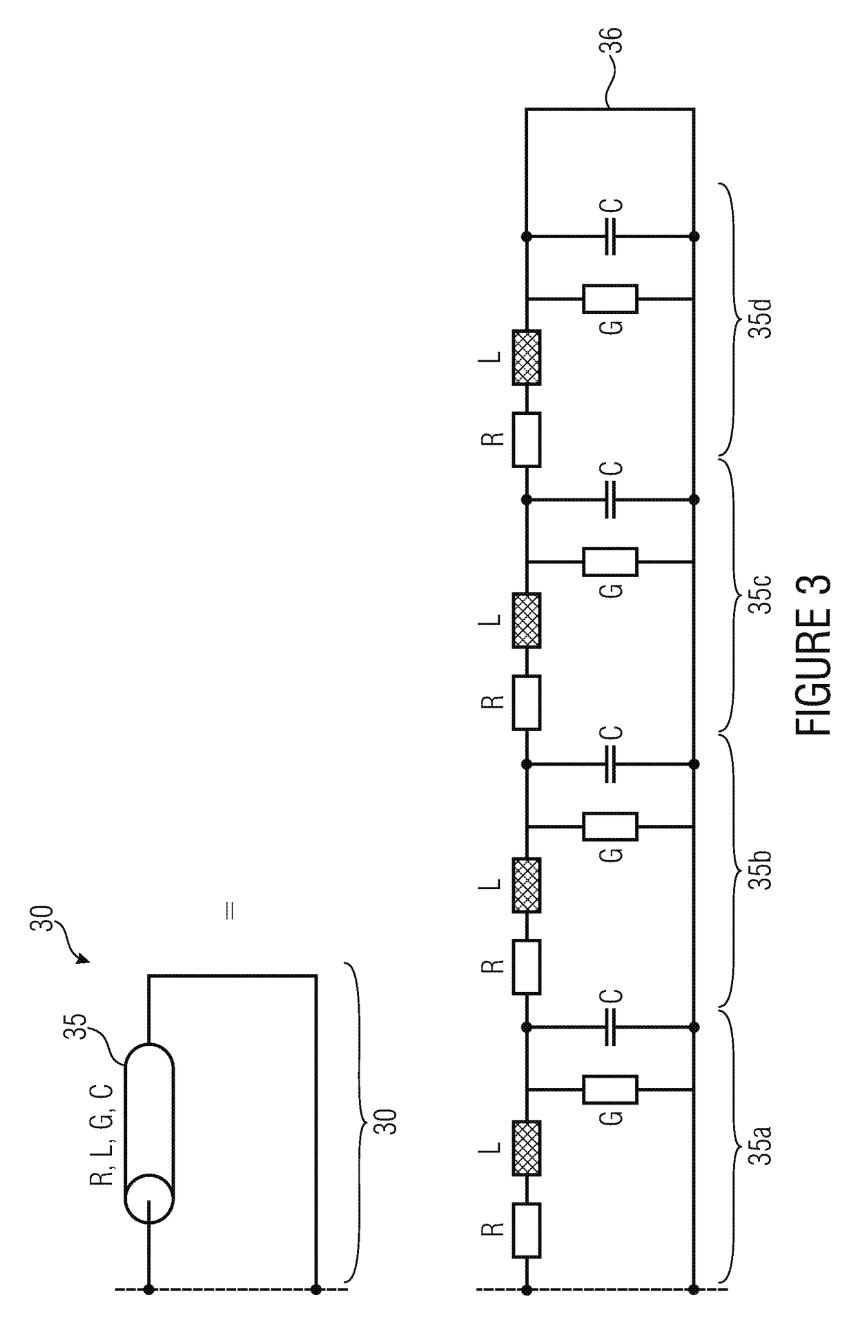
[0029]FIG. 1 schematically shows a simplified small-signal equivalent circuit diagram of an electroabsorption modulator 20 (EAM) comprising a driving source 10 and a terminating impedance circuit 30. In the example illustrated, the driving source 10 has been considered to be an ideal voltage source 11 and an internal resistor 12 of 50 ohm. The electroabsorption modulator 20 may, in a simplified manner, be represented by a capacitor Cmod. The terminating impedance circuit or additional wiring 30 mainly exhibits an ohmic (R) and inductive (L) behavior and typically has the object of avoiding reflections from the electroabsorption modulator 20 back to the source 10. Another object of the terminating impedance circuit may be power matchi...


PUM

PropertyMeasurementUnit
thicknessaaaaaaaaaa
thicknessaaaaaaaaaa
relative permittivity ∈raaaaaaaaaa

Abstract

A terminating impedance circuit, which is thermally decoupled from a substrate, for an electroabsorption modulator, having a modulator capacitance includes a series resistance-emphasized RF delay line exhibiting an impedance distributed over its length, wherein the spatially distributed impedance has at least a predominant resistance per unit length, an inductance per unit length tuned to the modulator capacitance, and a parasitic capacitance per unit length, wherein the resistance per unit length takes the function of a terminating resistor, wherein furthermore the inductance per unit length, together with the modulator capacitance, forms a strongly damped resonant circuit which provides, together with the terminating impedance circuit, for a controlled increase in the frequency response of the electroabsorption modulator within an operating frequency range, and wherein, at least for radio-frequency signals, the parasitic capacitance per unit length is negligible relative to the modulator capacitance.

Description

CROSS-REFERENCE TO RELATED APPLICATIONS[0001]This application is a continuation of copending International Application No. PCT / EP2014 / 068982, filed Sep. 5, 2014, which is incorporated herein by reference in its entirety, and additionally claims priority from German Application No. 10 2013 218 859.5, filed Sep. 19, 2013, which is incorporated herein by reference in its entirety.[0002]Embodiments of the present invention relate to a terminating impedance circuit for an electroabsorption modulator. Further embodiments relate to a method for electrically terminating an electroabsorption modulator. Some embodiments relate to a frequency-increasing drive wiring for electroabsorption modulators in an integrated form.BACKGROUND OF THE INVENTION[0003]Optical modulators by means of which a light beam may be modulated are, among other things, employed in optical telecommunications. The light beam may be transmitted through free space or through a light guide, such as, for example, a glass fibe...

Claims


Application Information

Patent Timeline
Patent Type & Authority Patents(United States)
IPC IPC(8): G02B6/00G02F1/015G02F1/15
CPCG02F1/015G02F2001/0155G02F1/0155
Inventor BACH, HEINZ-GUNTERMOEHRLE, MARTINPRZYREMBEL, GEORGES
Owner FRAUNHOFER GESELLSCHAFT ZUR FOERDERUNG DER ANGEWANDTEN FORSCHUNG EV
Why Eureka
Try Eureka