Plate material conveyance apparatus with temporary placement table

a technology of plate material and conveyance apparatus, which is applied in the direction of metal-working feeding devices, transportation and packaging, manufacturing tools, etc., can solve the problems of difficult to move the carriage at such a high speed, the stack of processed plate materials on the carriage may be likely to become unstuck, and the cycle time of plate material loading and unloading is reduced, and the installation space is small.

Active Publication Date: 2017-06-20
MURATA MASCH LTD
View PDF8 Cites 3 Cited by
  • Summary
  • Abstract
  • Description
  • Claims
  • Application Information

AI Technical Summary

Benefits of technology

[0010]In view of the foregoing, preferred embodiments of the present invention provide a plate material conveyance apparatus and a plate processing system, both of which have a reduced cycle time in plate material loading and unloading relative to the plate processing machine and require a relatively small space for installation.
[0016]As hereinabove described, during the plate processing machine performing the processing, the loader undergoes a loading preparation to deliver the unprocessed plate material and, on the other hand, the unloader performs an unloading preparation to transfer the processed plate material. Therefore, the wait time of the plate processing machine incident to the loading and unloading of the plate materials is significantly reduced or minimized. Also, since the region of travel of the loader and that of the unloader are different from each other, the operation of the loader and the operation of the unloader in no way interfere with each other. Therefore, the wait times of the loader and the unloader are significantly reduced or minimized. In view of the foregoing, the cycle time of plate material loading and unloading relative to the plate processing machine is significantly reduced. In addition, since the respective regions of travel of the loader and the unloader are arranged one above the other relative to each other, there is no need to secure respective large spaces of installation of the loader and the unloader on a horizontal plane.
[0017]Also, according to a preferred embodiment of the present invention, the processed plate material received from the unloader at the upper position of the unprocessed plate material placement unit is transported to the processed plate material placement unit by the temporary placement table. Since the temporary placement table is operable to pedestal the single processed plate material, it is light in weight as compared with a carriage on which a large number of processed plate materials are stacked. Also, since it is in a condition preceding the processed plate materials being stacked on the carriage, there is no problem associated with a displacement of the plate material on the temporary placement table. For this reason, the temporary placement table is configured to quickly slide between the unprocessed plate material placement unit and the processed plate material placement unit and, correspondingly, the cycle time of plate material loading and unloading is significantly reduced. Yet, when the temporary placement table is slid, a compact drive source is sufficient and therefore, the electric power consumption is significantly reduced or minimized.
[0019]The motion constraining member referred to above merely constrains the processed plate material from moving in the direction where the unprocessed plate material placement unit exists, and, therefore, it need not perform any complicated operation. For this reason, a mechanism configured to transfer the processed plate material on the temporary placement table onto the processed plate material placement unit is greatly simplified.
[0021]According to a plate processing system of a preferred embodiment of the present invention, the plate material conveyance apparatus operates as described above with the loading of the unprocessed plate material and the unloading of the processed plate material taking place relative to the plate processing machine. Accordingly, similarly as described above, the cycle time of plate material loading and unloading relative to the plate processing machine is significantly reduced and the processing efficiency is good. Also, there is no need to secure the large spaces for installation of the loader and the unloader in the horizontal place. In addition, when the temporary placement table is slid, a compact drive source is sufficient and the electric power consumption is significantly reduced.
[0023]Since the region of travel of the loader of the plate material conveyance apparatus and the region of travel of the unloader of the plate material conveyance apparatus are disposed one above the other, the first portion of the processing table, where the unprocessed plate material is mounted, and the second portion, where the processed plate material is unloaded, are commonized. Therefore, the dimension of the processing table in a horizontal direction perpendicular or substantially perpendicular to the direction of conveyance of the loader and the unloader is significantly reduced.

Problems solved by technology

However, since the carriage is moved while a number of the processed plate materials are stacked on such carriage, the weight is high.
Therefore, if such carriage is moved at a high speed, the stack of the processed plate materials on the carriage may be likely to become unstuck.
For this reason, it is difficult for the carriage to be moved at such a high speed and, hence, a problem tends to arise that the cycle time in plate material loading and unloading may be extended correspondingly.
Also, to move the carriage that is high in weight, a bulky driving source is required, resulting in the increase of electric power consumption.

Method used


Image

  • Plate material conveyance apparatus with temporary placement table
  • Plate material conveyance apparatus with temporary placement table
  • Plate material conveyance apparatus with temporary placement table

Examples


Embodiment Construction

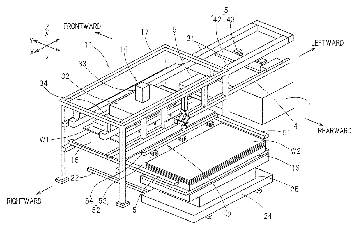
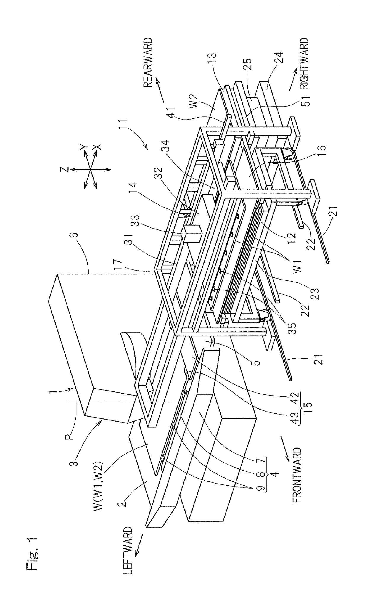
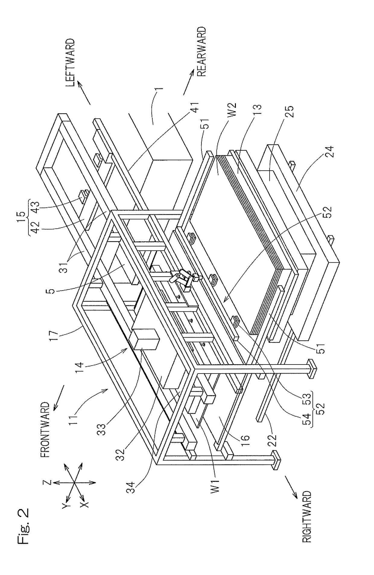
[0037]Preferred embodiments of the present invention will be described with reference to the accompanying drawings. In particular, FIG. 1 illustrates a perspective view of a plate processing system designed in accordance with a preferred embodiment of the present invention. The illustrated plate processing system includes a plate processing machine 1 and a plate material conveyance apparatus 11 disposed rightwardly next to the plate processing machine 1 as viewed from the front.

[0038]The plate processing machine 1 is, in this instance, preferably used in the form of a turret punch press and includes a processing table 2 on which a sheet metal or a plate material W to be processed is placed, a processing head 3 configured to process the plate material W placed on the processing table 2, and a plate material transport device 4 configured to transport the plate material W on and along the processing table 2. On one side of the processing table 2 adjacent the plate material conveyance a...


PUM


Abstract

A plate material conveyance apparatus, disposed next to a plate processing machine, includes an unprocessed plate material placement unit, a processed plate material placement unit, a loader, an unloader and a temporary placement table. The loader reciprocally moves between the unprocessed plate material placement unit and the plate processing machine to deliver an unprocessed plate material onto the plate processing machine. The unloader reciprocally moves in parallel to and below the loader between the unprocessed plate material placement unit and the plate processing machine, and delivers a processed plate material from the plate processing machine to the temporary placement table positioned above the unprocessed plate material placement unit. The temporary placement table slides between the unprocessed plate material placement unit and the plate processing machine, and transfers the processed plate material, received from the unloader, to the processed plate material placement unit.

Description

CROSS REFERENCE TO THE RELATED APPLICATION[0001]This application is based on and claims Convention priority to Japanese patent application No. 2012-094508, filed Apr. 18, 2012, the entire disclosure of which is herein incorporated by reference as a part of this application.BACKGROUND OF THE INVENTION[0002]1. Field of the Invention[0003]The present invention relates to a plate conveyance apparatus and a plate processing system using such plate conveyance apparatus, which are capable of loading an unprocessed plate material or sheet metal onto a plate processing machine and unloading a processed plate material from such plate processing machine.[0004]2. Description of the Related Art[0005]The plate material conveyance apparatus capable of loading unprocessed plate materials onto a plate processing machine such as, for example, a punch press and unloading the processed plate material from the plate processing machine is currently available in two types. One of the two types makes use o...

Claims


Application Information

Patent Timeline
Patent Type & Authority Patents(United States)
IPC IPC(8): B21D43/00B65H5/04B65H5/16B21D43/22B25J11/00B65H5/22B21D43/24B23Q7/04B21D43/13B23Q7/10
CPCB21D43/003B21D43/22B21D43/24B25J11/00B21D43/13B23Q7/04B23Q7/103B65H5/04B65H5/16B65H5/222
Inventor ICHIOKA, HIROKAZU
Owner MURATA MASCH LTD
Why Eureka
Try Eureka