Gear motor including reduction mechanism

a reduction mechanism and gear motor technology, applied in the direction of gearing, dynamo-electric machines, dynamo-electric components, etc., can solve the problems of significant restriction, inability to achieve size and weight reduction, and extremely strict restrictions, so as to prevent shaft instability and the like when unbalanced load occurs, the effect of significant speed reduction and high torque outpu

Active Publication Date: 2017-06-27
COPAL ELECTRON CO LTD
View PDF3 Cites 772 Cited by
  • Summary
  • Abstract
  • Description
  • Claims
  • Application Information

AI Technical Summary

Benefits of technology

[0015]As is clear from the description above, the present invention achieves the following effects:
[0016](1) According to a first aspect, the at least a single planetary two-stage gear including a small gear or a large gear that meshes together with a large gear or a small gear of the planetary two-stage gear is arrayed between the sun gear and the internal gear. Therefore, shaft instability and the like when unbalanced load occurs can be prevented with certainty. In addition, significant speed reduction and high torque output can be achieved. Thinness and size and weight reduction of the speed reduction section can be achieved.
[0017](2) According to a second aspect, in addition to effects similar to above-described (1) being achieved, because the gear ratio of the large gear and the small gear of the planetary two-stage gear is not an integral multiple, reduction ratio (gear ratio) of the overall reduction mechanism can be specifically set. Therefore, freedom in design can be significantly improved.
[0018]In other words, an opportunity for selecting a desired gear ratio in relation to a determined outer diameter (size) can be obtained.
[0019](3) According to a third aspect, in addition to effects similar to above-described (1) and (2) being achieved, because the planetary two-stage gear is arrayed in a horizontal direction such that the positional relationship of the small gear or the large gear of the planetary two-stage gear is reversed upside down, the reduction ratio can be increased without increase in thickness.
[0020](4) According to a fourth aspect, in addition to effects similar to above-described (1) to (3) being achieved, because the modules (tooth size) of the large gear and the small gear of the planetary two-stage gear are set to differing values, and the module value of a gear (any of the sun gear, the internal gear, the planetary two-stage gear, and a planetary gear) that meshes with the large gear or the small gear of the planetary two-stage gear movement is set to match, further size reduction can be achieved while maintaining rotation smoothness.

Problems solved by technology

However, in a system such as this, although high torque output can be achieved, there is a disadvantage in that size and weight reduction cannot be achieved.
However, various conditions (such as geometric conditions, adjacency conditions, and assembly conditions) apply to the design of a planetary gear mechanism, thereby significantly limiting the degree of freedom in design thereof.
In particular, extremely strict restrictions are set by the assembly conditions for enabling all planetary gears to correctly mesh with a sun gear and an internal gear.
There is a disadvantage in that the combinations of the numbers of teeth and the reduction ratio that can be selected are significantly limited.

Method used


Image

  • Gear motor including reduction mechanism
  • Gear motor including reduction mechanism
  • Gear motor including reduction mechanism

Examples


first embodiment

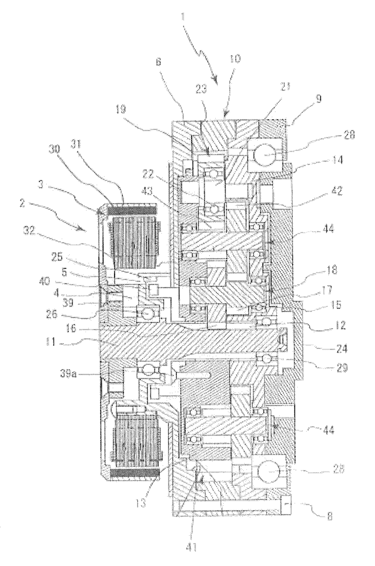
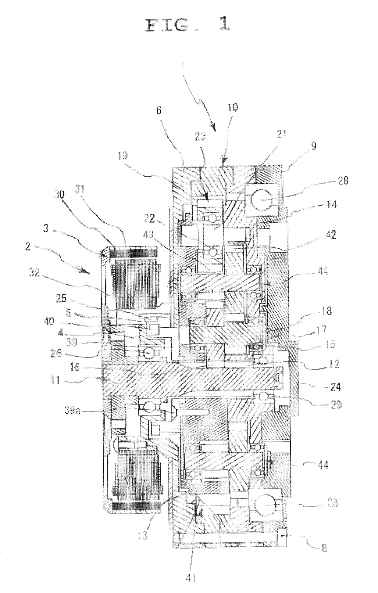
[0107]In addition, the sun gear 12 and the large gears 16, 16, and 16 of the first planetary two-stage gears 18, 18, and 18 are composed of helical gears. However, spur gears or double helical gears may also be used. The other gears may also similarly be any of spur gears, helical gears, and double helical gears.

[0108]Furthermore, it is known that the module (tooth size) may be set to a low value regarding a gear with a small load. In the present invention, the respective modules of the large gears 16, 16, and 16 and the small gears 17, 17, and 17 of the first planetary two-stage gears 18, 18, and 18 are set to differing values. In addition, the module value of the large gears 16, 16, and 16 and the module value of the sun gear 12 with which the large gears 16, 16, and 16 mesh are matched. The module value of the small gears 17, 17, and 17 and the module value of the large gears 42, 42, and 42 of the second planetary two-stage gear 44 wish which the small gears 17, 17, and 17 mesh ...

second embodiment

[0115]FIG. 14 schematically shows the combination of gears in a manner similar to FIG. 13.

[0116]The second embodiment for carrying out the present invention, shown in FIG. 14, mainly differs from the first embodiment for carrying out the present invention in that third planetary two-stage gears 47, 47, and 47 that include large gears 45, 45, and 45 that mesh with the small gears 43, 43, and 43 of the second planetary two-stage gears 44, 44, and 44 are arrayed in a horizontal direction such that the positional relationship between the small gears 43, 43, and 43 and the large gears 45, 45, and 45 is reversed upside down. As a result of the third planetary two-stage gears 47, 47, and 47 being arrayed in this way, the reduction ratio can be further increased without increase in the thickness of the reduction mechanism 41.

[0117]In addition, according to the first and second embodiments, the planetary gears 23, 23, and 23 may be omitted. In this case, according to the first embodiment, t...


PUM


Abstract

The present invention provides a reduction mechanism in which high torque output can he achieved, thinness and size and weight reduction can be achieved, and the number of teeth of a gear and reduction ratio can be freely set. In a gear motor that includes a reduction mechanism in which a planetary two-stage gear is arrayed between a sun gear of a planetary gear mechanism and an internal gear of a planetary gear mechanism, the reduction mechanism has at least a single planetary two-stage gear arrayed such as to be positioned between the sun gear and the internal gear and including a small gear or a large gear that meshes together with a large gear or a small gear of the planetary two-stage gear, and both end portions of the at least a single planetary two-stage gear are supported by ball bearings.

Description

BACKGROUND OF THE INVENTION[0001]1. Field of the Invention[0002]The present invention relates to a reduction mechanism for a gear motor or the like having high torque output and used in a muscle force assisting device or the like.[0003]2. Description of the Related Art[0004]Conventionally, a gear motor that has high torque output uses a multistage planetary gear system in which planetary gear mechanisms are stacked together in two stages and a reduction ratio is obtained.[0005]However, in a system such as this, although high torque output can be achieved, there is a disadvantage in that size and weight reduction cannot be achieved.[0006]Therefore, a compound planetary gear mechanism formed by the elements of two planetary gear mechanisms being joined in a planar manner is considered.[0007]However, various conditions (such as geometric conditions, adjacency conditions, and assembly conditions) apply to the design of a planetary gear mechanism, thereby significantly limiting the degre...

Claims


Application Information

Patent Timeline
Patent Type & Authority Patents(United States)
IPC IPC(8): F16H57/08F16H1/36H02K7/116F16H1/28
CPCF16H1/36F16H1/28H02K7/116
Inventor KANAI, TAKASHITANAKA, YUSUKEMATSUSHITA, HIROKIENDO, TAKAYUKI
Owner COPAL ELECTRON CO LTD
Why Eureka
Try Eureka