Device for discharging liquid

a technology for discharging liquid and liquid, which is applied in the direction of transportation hydrogen technology, electrochemical generators, separation processes, etc., can solve the problems of inability and inability to be susceptible to contamination, and achieve the effect of safe and reliable discharging of liquid without high hydrogen emissions to the environmen

Active Publication Date: 2017-06-27
CELLCENTRIC GMBH & CO KG
View PDF14 Cites 1 Cited by
  • Summary
  • Abstract
  • Description
  • Claims
  • Application Information

AI Technical Summary

Benefits of technology

[0008]It is an object of the present invention to propose a device for discharging liquid water from a water separator in a fuel cell system, which d

Problems solved by technology

It functions securely and reliably and is very unsusceptible with regard

Method used


Image

  • Device for discharging liquid
  • Device for discharging liquid

Examples


Embodiment Construction

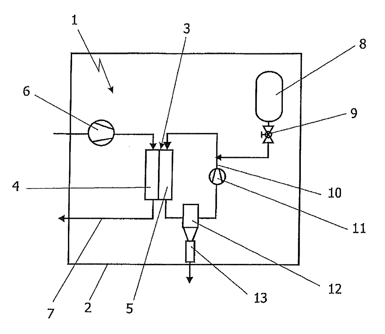
[0023]In the illustration of FIG. 1, a greatly schematized fuel cell system 1 is shown in a schematically indicated vehicle 2. The fuel cell system 1 serves for providing electrical power for the vehicle 2, in particular driving power for the vehicle 2. It consists substantially of a fuel cell 3 which has a cathode chamber 4 and an anode chamber 5. The cathode chamber 4 is supplied in a manner known per se with air as oxygen supplier via an air supply device 6. The exhaust air leaves the system again via an exhaust air line 7. For simplifying the illustration, further components which are generally known and common in the region of air supply such as, for example, air filter, humidifiers and the like are omitted. This applies also to components in the region of the exhaust air line, for example a turbine for recovering residual energy in the exhaust air.

[0024]The anode chamber 5 of the fuel cell 3 is supplied with hydrogen from a compressed gas storage 8 via a pressure control and m...


PUM

PropertyMeasurementUnit
Temperatureaaaaaaaaaa
Timeaaaaaaaaaa
Poweraaaaaaaaaa

Abstract

A device (13) for discharging liquid water from a water separator (12) in a fuel cell system (1), having a valve device (15), a liquid sensor (16) and a control unit (17) which controls the valve device (15) depending on measured values of the liquid sensor (16). The liquid sensor (16) is arranged downstream of the valve device (15) in the flow direction.

Description

BACKGROUND OF THE INVENTION[0001]Field of the Invention[0002]The invention relates to a device for discharging liquid from a water separator in a fuel cell system according to the kind defined in greater detail in the preamble of claim 1. The invention further relates to a method for discharging liquid from a water separator in a fuel cell system by means of such a device.[0003]Description of the Related Art[0004]Fuel cell systems are known from the prior art. The functionality is in essence that electrical energy and product water is produced from hydrogen and oxygen. Here, the resulting product water together with exhaust gases is discharged from the region of the fuel cell. In order to separate the liquid water from these exhaust gases, water separators are typically provided in the fuel cell systems. Hereby, on the one side, liquid water can be prevented from escaping from the fuel cell system and, on the other, potential freezing of line elements due to said liquid water can be...

Claims


Application Information

Patent Timeline
IPC IPC(8): H01M8/04291H01M8/04089B01D5/00H01M8/04119H01M8/0432H01M8/04492
CPCH01M8/04156B01D5/00H01M8/04097H01M8/04164H01M8/04291H01M8/04373H01M8/04514H01M2250/20Y02T90/32Y02E60/50Y02T90/40
Inventor MUETSCHELE, ARMINSCHMALZRIED, SVENSTEINHUEBL, SIMONTEVES, HARALD
Owner CELLCENTRIC GMBH & CO KG
Why Eureka
Try Eureka