
Apparatus and system for controlling window coverings to adjust admitted daylight

a technology of window covering and window covering, applied in the direction of programme control, transmission, building components, etc., can solve the problems of insufficient implementation and installation of automatic window coverings, limitation and relative high cost of existing, and the prior art automatic window covering design that provides the required robustness of design and functionality to achieve benefits is too expensive, and achieves energy efficiency and cost-effective

Active Publication Date: 2017-07-04
ELEMENT RICHARD GERAINT
View PDF15 Cites 13 Cited by
  • Summary
  • Abstract
  • Description
  • Claims
  • Application Information

AI Technical Summary

Benefits of technology

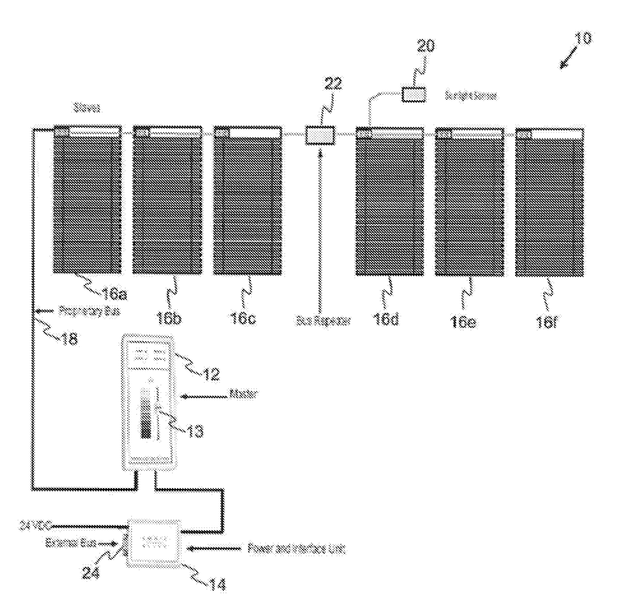
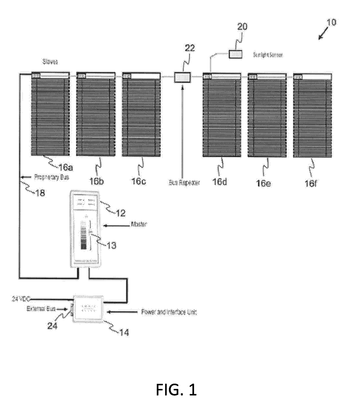
[0019]In another aspect, the present disclosure relates to an apparatus for controlling slat based window coverings to adjust admitted daylight, said apparatus characterized in that it comprises: a master circuitry incorporating a microcontroller; one or more blinds positioned by one or more windows, said one or more blinds being connected to a motor operable as one or more slaves controlled by the master circuitry; and one or more sunlight intensity sensors operable to detect sunlight intensity directed to the one or more windows and to communicate sunlight intensity data to the master circuitry, the master circuitry being operable to control the adjustment of one or more of the one or more slat based window coverings in accordance with the sunlight intensity data by way of the microcontroller to avert undesirable solar heat gains and achieve daylight harvesting.
[0027]Said apparatus of the present invention may further be an embodiment that is characterized by the microcontroller being operable to utilize the signals transmitted by the one or more slaves to determine that one or more of the one or more blinds is malfunctioning and to generate commands and transmits said commands to the one or more blinds that is malfunctioning to correct said malfunction in a manner that averts damage to the one or more blinds.
[0032]Said energy efficient system of the present invention may further be an embodiment that is characterized by the master module being configured to detect the position of each slat based window covering via the one or more slave modules, and to initiate correction of any positional errors reported by the one or more slave modules.
[0037]Said energy efficient system of the present invention may further be an embodiment that is characterized by the control of the master module achieving operation of the system that is energy efficient and cost-effective.

Problems solved by technology

Despite numerous designs and strategies that have been introduced at points in time over many decades, automated window coverings have not been implemented and installed in quantities that are commensurate with the perceived benefits of automated window coverings.
This is due in large part to the limitations and relative high cost of existing, known prior art automated window covering designs.
As an example, typically prior art automated window covering designs that provide the required robustness of design and functionality to achieve benefits are too expensive.
The high cost of such automated window covering designs mean that they are unlikely to be implemented, due to the fact that a reasonable payback period cannot be achieved.
Rollershades are frequently considered less desirable for sunlight control or daylight harvesting than slat based window covering devices.
The variance of transmissivity levels in a window that is covered partially by a rollershade can create an undesirable situation.
The result may be that full sunlight streams unimpeded through the bottom portion of a window despite the fact that the rollershade has been dropped to cover the majority of the window.
This can lead to undesirable solar heat gains occurring through the uncovered portion of the window.
Such a window covering may further cause a loss of opportunity for daylight harvesting through the covered portion of the window.
The lift function of such systems may add a significant cost to the system, and this cost may not be justified as it may not be commensurate with any payback or return on the investment in the installation of a tilt and lift system that is realized through the reduction of a building's energy consumption due to the installation of such a system.
More complex control systems may utilize rotary encoders utilizing optical interrupters and opto-couplers.
A significant drawback of such prior art systems is that they typically require calibration in situ, as well as periodic recalibration.
Such systems may also suffer from drift.
Prior art systems may experience a loss of positional information during a power outage.
Such systems are complex, and are often too expensive for home automation.
There are further drawbacks to prior art automated window covering systems which also attribute to the lack of widespread installation of such systems.
One such drawback is that the efficacy of prior art automated window covering systems can be easily defeated.
Another drawback of prior art automated window covering systems is that although designs that are less expensive may be appealing from a price perspective, such designs frequently have limited functionality.
The limited functionality of the prior art automated window covering systems has the result that such systems are deemed to be unsuitable for commercial operations.
This is a significant drawback in that the bulk of the perceived benefits from the installation of automated window covering systems are considered to be in installation of such systems for commercial operations.

Method used


Image

  • Apparatus and system for controlling window coverings to adjust admitted daylight
  • Apparatus and system for controlling window coverings to adjust admitted daylight
  • Apparatus and system for controlling window coverings to adjust admitted daylight

Examples


Embodiment Construction

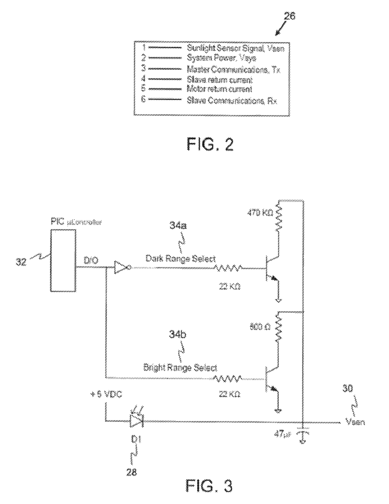
[0064]The present invention is an apparatus, system, method, computer program, and computer program product for controlling window coverings to adjust admitted daylight. The present invention comprises a control system for controlling the amount of daylight admitted through adjustable window coverings. In an embodiment of the present invention, the system includes a stand-alone open loop proportional control subsystem including a calculation or algorithm that is operable to convert a sunlight sensor signal to a blind slat position based on a predetermined curve stored in memory. In another embodiment of the present invention, the system is operable to transmit the sunlight sensor information, for example, such as in Lux, to an external system, which may then provide blind slat position requests based on some other curve, algorithm, or user need. The blind slat position may be controlled by the system to avert undesirable solar heat gains and also achieve significant daylight harvest...


PUM


Abstract

The present invention is an apparatus, system, method, computer program, and computer program product for controlling window coverings to adjust admitted daylight. More particularly, the present disclosure plates to a control system for controlling the amount of daylight admitted through adjustable window coverings. In an embodiment of the present invention, the system includes a stand-alone open loop proportional control subsystem including a calculation or algorithm that is operable to convert a sunlight sensor signal to a blind slat position based on a predetermined curve stored in memory. In another embodiment of the present invention, the system is operable to transmit the sunlight sensor information, for example, such as in Lux, to an external system, which may then provide blind slat position requests based on some other curve, algorithm, or user need. The blind slat position may be controlled by the system to avert undesirable solar heat gains and also achieve significant daylight harvesting.

Description

FIELD OF THE INVENTION[0001]The present invention relates generally to an apparatus and system for controlling window coverings to adjust admitted daylight, and more particularly to a control system for controlling the amount of daylight admitted through adjustable window coverings.BACKGROUND OF THE INVENTION[0002]Numerous studies and publications have shown the benefits of automating window coverings and, in particular, it is well known that automated window coverings can greatly improve the energy efficiency of commercial buildings by reducing heating and cooling loads. These benefits can also extend to residential applications with the added benefits of enhanced security and convenience. The benefits of daylighting control, whereby daylight is harvested and augmented by artificial lighting when necessary are also known. However, the benefits of daylighting control systems have been shown to be highly dependent upon the efficacy of an automated window covering system that works in...

Claims


Application Information

Patent Timeline
Patent Type & Authority Patents(United States)
IPC IPC(8): G05B11/01H04L12/28G05B15/02E06B9/322E06B9/32H04L12/403
CPCG05B11/01E06B9/32E06B9/322G05B15/02H04L12/2829H04L12/403G05B2219/163G05B2219/2653H04L2012/285
Inventor ELEMENT, RICHARD GERAINT
Owner ELEMENT RICHARD GERAINT
Learn More