Image forming apparatus correcting unevenness of potential distribution due to change of exposure spot shape of light beam on photosensitive member

a technology of image forming apparatus and light beam, which is applied in the direction of electrographic process apparatus, printing, instruments, etc., can solve the problem of uneven density of output image, and achieve the effect of reducing image quality

Active Publication Date: 2017-07-11
CANON KK
View PDF15 Cites 30 Cited by
  • Summary
  • Abstract
  • Description
  • Claims
  • Application Information

AI Technical Summary

Benefits of technology

[0008]With the invention, the decrease in image quality due to the unevenness of the spot shape of the laser light in the main-scanning direction can be restricted by correcting the image data with use of the two-dimensional filter.

Problems solved by technology

Even if the photosensitive member is exposed to laser light with the same light quantity, the density of an output image may be uneven due to the unevenness of the photosensitive characteristics of the surface of the photosensitive member.

Method used


Image

  • Image forming apparatus correcting unevenness of potential distribution due to change of exposure spot shape of light beam on photosensitive member
  • Image forming apparatus correcting unevenness of potential distribution due to change of exposure spot shape of light beam on photosensitive member
  • Image forming apparatus correcting unevenness of potential distribution due to change of exposure spot shape of light beam on photosensitive member

Examples


first embodiment

[0030]An embodiment of an electrophotographic color image forming apparatus as an example is described below. It is to be noted that the embodiment is not limited to the color image forming apparatus, and may be a monochrome image forming apparatus.

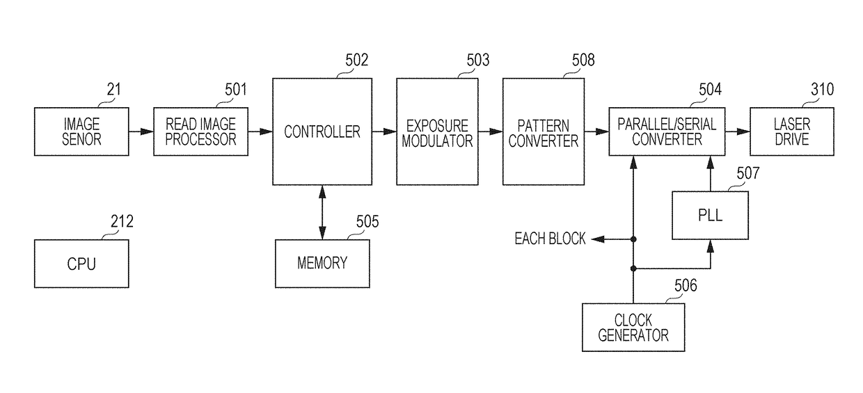
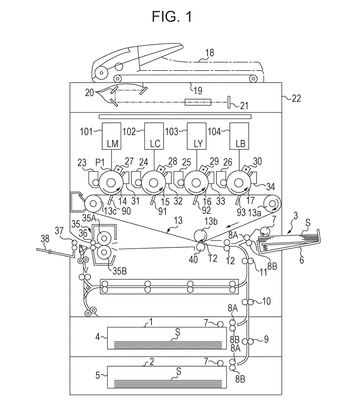
[0031]FIG. 1 is a schematic cross-sectional view of the color image forming apparatus. The color image forming apparatus shown in FIG. 1 includes a reading device 22. The reading device 22 includes an ADF 18 (Auto Document Feeder), a document plate 19, a reflecting mirror group 20, and an image sensor 21. The ADF 18 conveys a document set at a predetermined position to the document plate 19. The reading device 22 includes an illuminating device (not shown). The illuminating device irradiates a document conveyed to the document plate 19 from the ADF 18 or a document placed on the document plate 19 with light. The light reflected from the document is guided by the reflecting mirror group 20 to the image sensor 21. The image sensor 21 includ...

second embodiment

[0085]In this embodiment, a configuration that corrects image data, the configuration which is different from the second embodiment, is described. The configuration other than the exposure modulator is the same, and hence the description for the configuration other than the exposure modulator is omitted.

[0086]FIG. 13 shows a control block diagram of an image forming apparatus according to this embodiment. A ROM 1303 stores filter coefficients corresponding to respective positions (or respective regions) in the main-scanning direction. The filter coefficients are filter coefficients in a matrix centered at a target pixel and respectively correspond to the target pixel and surrounding pixels. A data reading unit 1302 reads out the filter coefficients in the matrix corresponding to the respective positions in the main-scanning direction from the ROM 1303 and writes the filter coefficients in a register in a two-dimensional filter 1301, on the basis of the count value of the main-scanni...

third embodiment

[0100]This embodiment relates to a technique of setting the exposure amount of each pixel on the basis of the previously measured spot shapes at plural longitudinal positions similarly to the second embodiment. In particular, a point different from the second embodiment is described in detail.

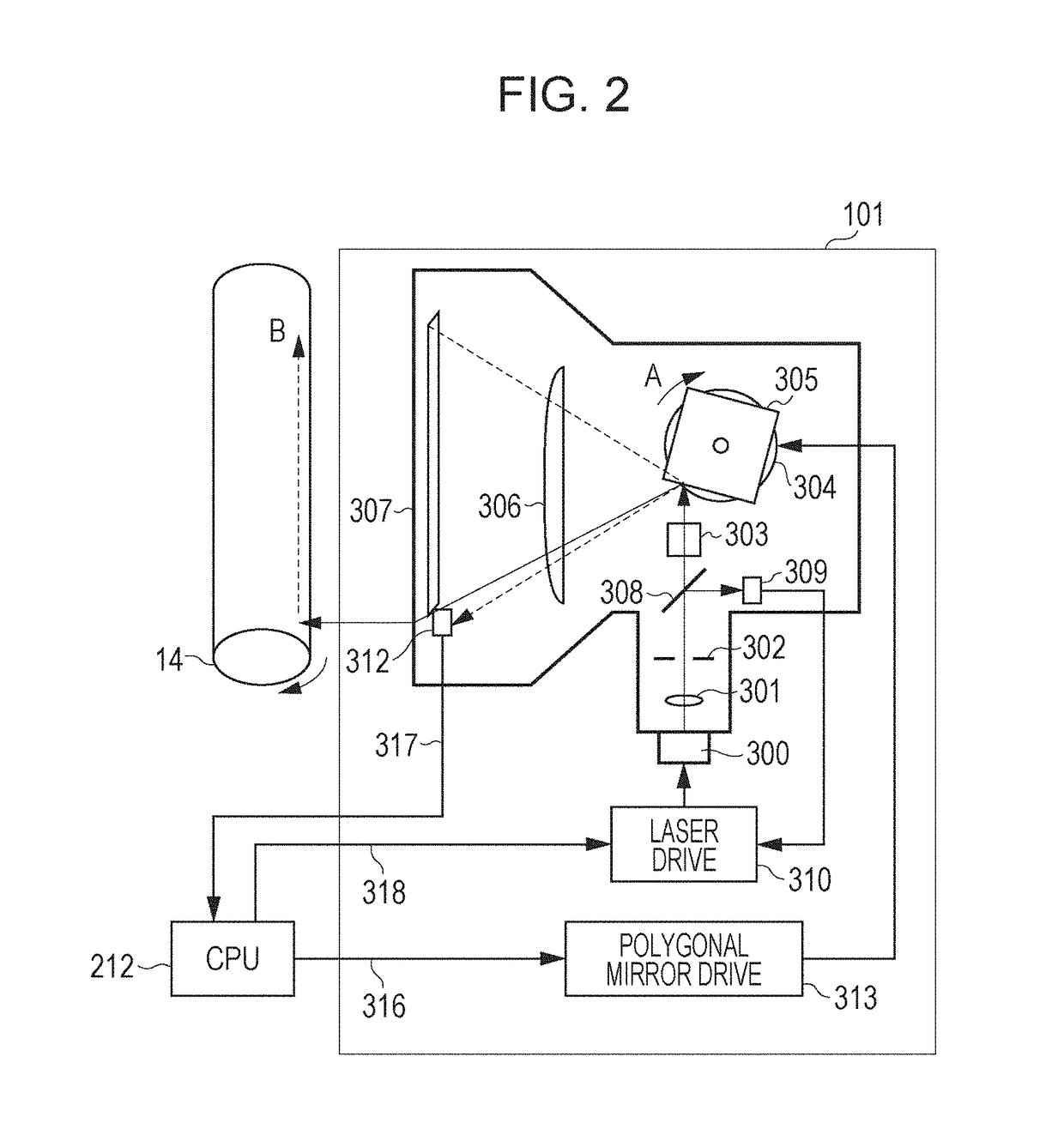
[0101]In this embodiment, when the spot shape varies with a temperature change in the apparatus, proper correction is made in accordance with the temperature. Members configuring optical scanning devices 101, 102, 103, and 104 are expanded (or contracted) due to a temperature change. Then, the optical path length until laser light reaches the surface of the photosensitive drum is changed, and defocusing may occur. At this time, as shown in FIG. 18, the spot shape is changed in accordance with the defocusing amount. As the defocusing is increased, the light intensity at the spot center is decreased and simultaneously the light intensity in the surrounding portion is increased. Hence, the spot sh...


PUM


Abstract

An incidence angle of laser light with respect to a photosensitive member in a main-scanning direction is different depending on an exposure position. Hence, the spot shape of the laser light on the photosensitive member is different in the main-scanning direction. A filter coefficient is changed in the main-scanning direction, and image data is corrected with the filter coefficient.

Description

TECHNICAL FIELD[0001]The present invention relates to an electrophotographic image forming apparatus, such as a digital copier, a multifunction device, or a laser printer.BACKGROUND ART[0002]An electrophotographic image forming apparatus forms an image by developing an electrostatic latent image formed on a photosensitive member with a toner. The image forming apparatus includes an optical scanning device. An electrostatic latent image is formed on the photosensitive member by scanning with laser light emitted from the optical scanning device on the basis of image data. The optical scanning device includes a rotatable polygonal mirror that deflects laser light emitted from a light source, and an optical member such as a lens or a mirror that guides the laser light deflected by the rotatable polygonal mirror onto the photosensitive member.[0003]The photosensitive characteristics of the surface of the photosensitive member slightly vary depending on the position of the surface of the ...

Claims


Application Information

Patent Timeline
Patent Type & Authority Patents(United States)
IPC IPC(8): G03G15/00B41J2/47G03G15/043G02B26/12G03G15/04
CPCG03G15/043B41J2/471G02B26/127G03G15/04072
Inventor HORIUCHI, IZURUTAKIKAWA, YOICHIHIRABAYASHI, JUN
Owner CANON KK
Why Eureka
Try Eureka