Pulsed radar level gauging with efficient start-up

a pulsed, radar technology, applied in the direction of reradiation, liquid/fluent solid measurement, engine lubrication, etc., can solve the problems of hard to meet the safety requirements regarding power usage and energy storage, the amount of energy allowed to be stored, etc., to save power used for those measurements, the effect of energy-consuming signal handling

Active Publication Date: 2017-07-18
ROSEMOUNT TANK RADAR
View PDF61 Cites 0 Cited by
  • Summary
  • Abstract
  • Description
  • Claims
  • Application Information

AI Technical Summary

Benefits of technology

[0018]Another advantage of the present invention is that energy consuming signal handling and processing to correct the level measurement due to an unstable or incorrect frequency separation will not be needed or at least minimized.
[0019]It should be noted that the frequency separation normally is in the order of Hz, e.g. around 4 Hz. Using a conventional feedback regulator, the regulation frequency will be in the same order, and it will therefore typically take several seconds to ensure a stable frequency separation. A measurement cycle is typically much shorter, in the order of ms, and there will thus be a number of measurement cycles which do not provide a level measurement until the frequency separation is properly stabilized. With the present invention, the power which would be used for those measurements can be saved and thereby a more power efficient radar level gauge system is provided with a number of inherent advantages.
[0020]Even in cases where a more time efficient frequency regulation is employed, the power savings provided by the present invention can be important.
[0021]The advantages of the invention are particularly important in situations where available power is scarce, such as for a radar level gauge system without any connection to a remote power supply, and having a local energy store (e.g. a battery) as only means to provide power. To keep the maintenance cost of the level gauge system down, battery life should be as long as possible, preferably in the order of several years or even up towards a decade. This means that it is important to design the level gauge system for a very low average energy consumption, without compromising the performance of the level gauge system in terms of, for example, accuracy and ability to monitor changes in the tank. In other words, one advantage related to this way of handling the power management is a lowered energy consumption which in turn enables a battery powered radar level gauge system to operate for a longer period of time without depleting the battery.
[0022]A simple way to evaluate the frequency separation is to detect it directly. For example, the frequency separation evaluation circuit may be configured to compare a detected frequency separation to a predefined threshold value in order to determine a good timing of said frequency separation. Herein, the term “good timing of the frequency separation” refers to that the frequency separation is sufficiently stable over time and / or that the frequency separation is sufficiently small. When a good timing of the frequency separation has been determined, the frequency separation evaluation circuit will generate the power-up signal in order to activate more parts of the system.
[0023]Another way to evaluate the frequency separation is to detect a condition of the frequency regulator. For example, an error signal indicative of a difference between a current frequency separation and the predefined frequency separation can be used to evaluate when the frequency separation is stable.

Problems solved by technology

However, current radar level gauge systems are still power hungry and it is hard to meet safety requirements regarding power usage and energy storage.
Even further, there is a need to meet the above mentioned safety regulations limiting the amount of energy which is allowed to be stored due to inherent hazards such as the material in the storage tanks being highly flammable etc.

Method used


Image

  • Pulsed radar level gauging with efficient start-up
  • Pulsed radar level gauging with efficient start-up
  • Pulsed radar level gauging with efficient start-up

Examples


Embodiment Construction

[0033]In the present detailed description, various embodiments of the level gauge system according to the present invention are mainly discussed with reference to a pulsed radar level gauge system of the non-contact type, in which an electromagnetic signal is propagated towards the product contained in the tank using a propagating device in the form of a radiating antenna, such as a cone antenna, a horn antenna, an array antenna or a patch antenna.

[0034]It should be noted that this by no means limits the scope of the present invention, which is equally applicable to a pulsed guided wave radar (GWR) level gauge system utilizing a propagating device in the form of a transmission line probe, such as a single line probe (including a so-called Sommerfeld or Goubau probe), a two-lead probe, a coaxial probe, etc.

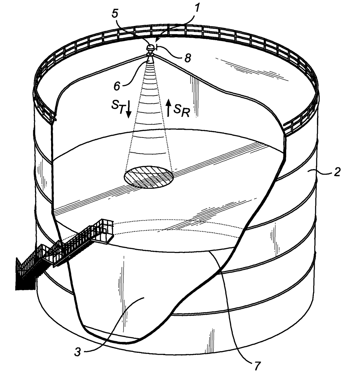
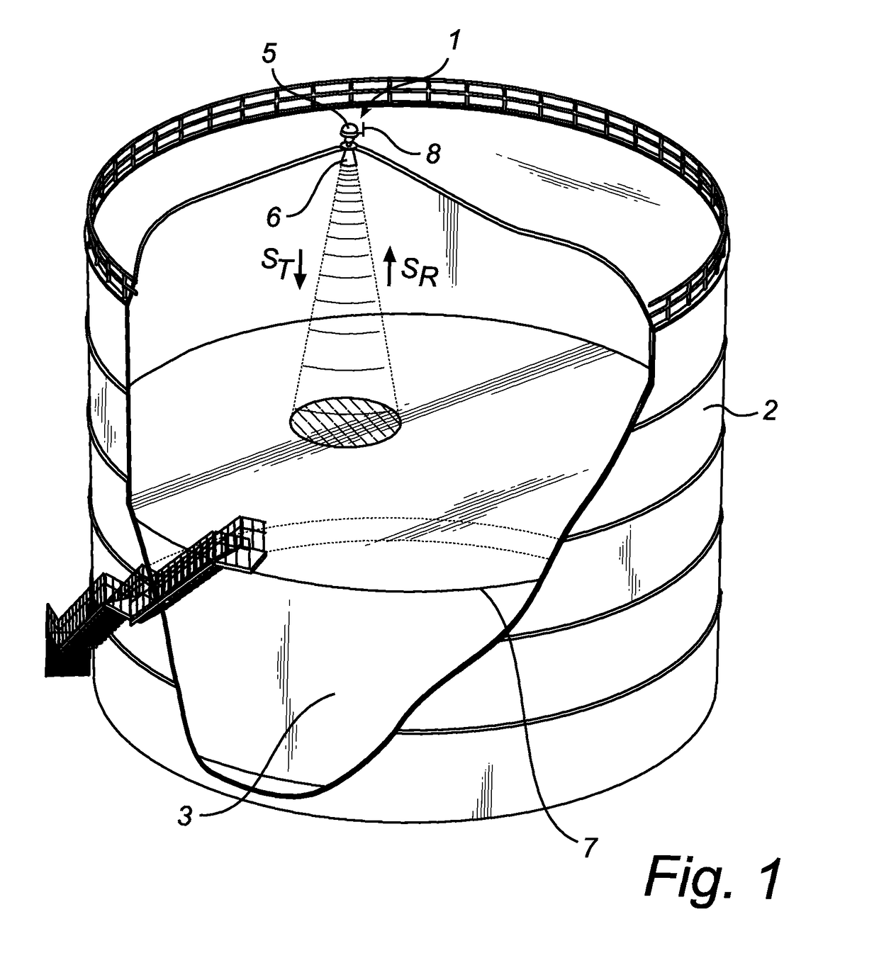
[0035]FIG. 1 schematically illustrates a level gauge system 1 arranged on top of a tank 2 for determining the filling level of a product 3 contained in the tank 2 using microwaves....


PUM


Abstract

A method for powering a radar level gauge, comprising an initial frequency stabilization procedure, ensuring a stable separation frequency between a first and a second clock frequencies, during which frequency stabilization procedure said radar level gauge is not powered to provide a level output, and a subsequent measurement cycle, performed only when a stable separation frequency has been established, during which said radar level gauge is powered to provide a level output. The present invention allows a radar level gauge system to save power by not providing power to and operating the radar level gauge circuit during such times when the frequency separation would not enable the radar level gauge to provide proper level measurements.

Description

FIELD OF THE INVENTION[0001]The present invention relates to the field of radar level gauge systems using pulsed measurements. In particular, the present invention relates to power management within a radar level gauge system.BACKGROUND OF THE INVENTION[0002]Radar level gauge (RLG) systems are in wide use for determining the filling level of a product contained in a tank. Radar level gauging is generally performed either by means of non-contact measurement, whereby electromagnetic signals are radiated towards the product contained in the tank, or by means of contact measurement, often referred to as guided wave radar (GWR), whereby electromagnetic signals are guided towards and into the product by a probe acting as a waveguide. The probe is generally arranged to extend vertically from the top towards the bottom of the tank. The probe may also be arranged in a measurement tube, a so-called chamber that is connected to the outer wall of the tank and is in fluid connection with the ins...

Claims


Application Information

Patent Timeline
Patent Type & Authority Patents(United States)
IPC IPC(8): G01F23/284G01S13/88G01S7/28G01S13/10
CPCG01F23/284G01S7/28G01S13/10G01S13/88
Inventor NILSSON, LEIFNYBERG, HAKANDELIN, HAKAN
Owner ROSEMOUNT TANK RADAR
Why Eureka
Try Eureka