Measurement of oxygen

a technology of oxygen measurement and oxygen, applied in the direction of fluorescence/phosphorescence, analysis by material excitation, instruments, etc., can solve the problems of reducing the life of the inert gas generation system on board, limiting the operation of open-loop, and implementing at a cost of bleed air and power higher demands on the propulsion and environmental systems

Active Publication Date: 2017-07-18
INNOVATIVE SCI SOLUTIONS
View PDF17 Cites 8 Cited by
  • Summary
  • Abstract
  • Description
  • Claims
  • Application Information

AI Technical Summary

Benefits of technology

[0007]The illumination source can include a red LED and a blue or UV LED, and the red and blue / UV LEDs can provide light energy to both the sampling and the reference probes and wherein the blue / UV LED may be used to create a fluorescent emission from the sampling and reference probes that passes through a long-pass filter corresponding an oxygen quenching at each of the probes, and the red LED may provide a reflected light signal from the sampling and reference probes that is transmitted to the detector through a long-pass filter to establish and eliminate a system phase lag not associated with fluorescence from the sampling and reference probes.

Problems solved by technology

Fuel tank inerting systems have long been used in tactical aircraft, but are typically restricted to open-loop operation.
While open-loop inerting systems provide an effective method of inerting the ullage in a fuel tank, such systems are implemented at a cost of higher demands on the propulsion and environmental systems for bleed air and power, and reduced life of the On-board Inert Gas Generation System (OBIGGS).
Further, inexpensive, compact oxygen sensors that may be effective for less volatile closed-loop automotive and industrial applications generally are not compatible with the highly combustible ullage environment of a tactical aircraft.
This intrinsic safety requirement generally limits OBIGGS systems to open-loop operations, whether applied to military or commercial aircraft.

Method used


Image

  • Measurement of oxygen
  • Measurement of oxygen
  • Measurement of oxygen

Examples


Embodiment Construction

[0035]In the following detailed description of the preferred embodiment, reference is made to the accompanying drawings that form a part hereof, and in which is shown by way of illustration, and not by way of limitation, a specific preferred embodiment in which the invention may be practiced. It is to be understood that other embodiments may be utilized and that changes may be made without departing from the spirit and scope of the present invention.

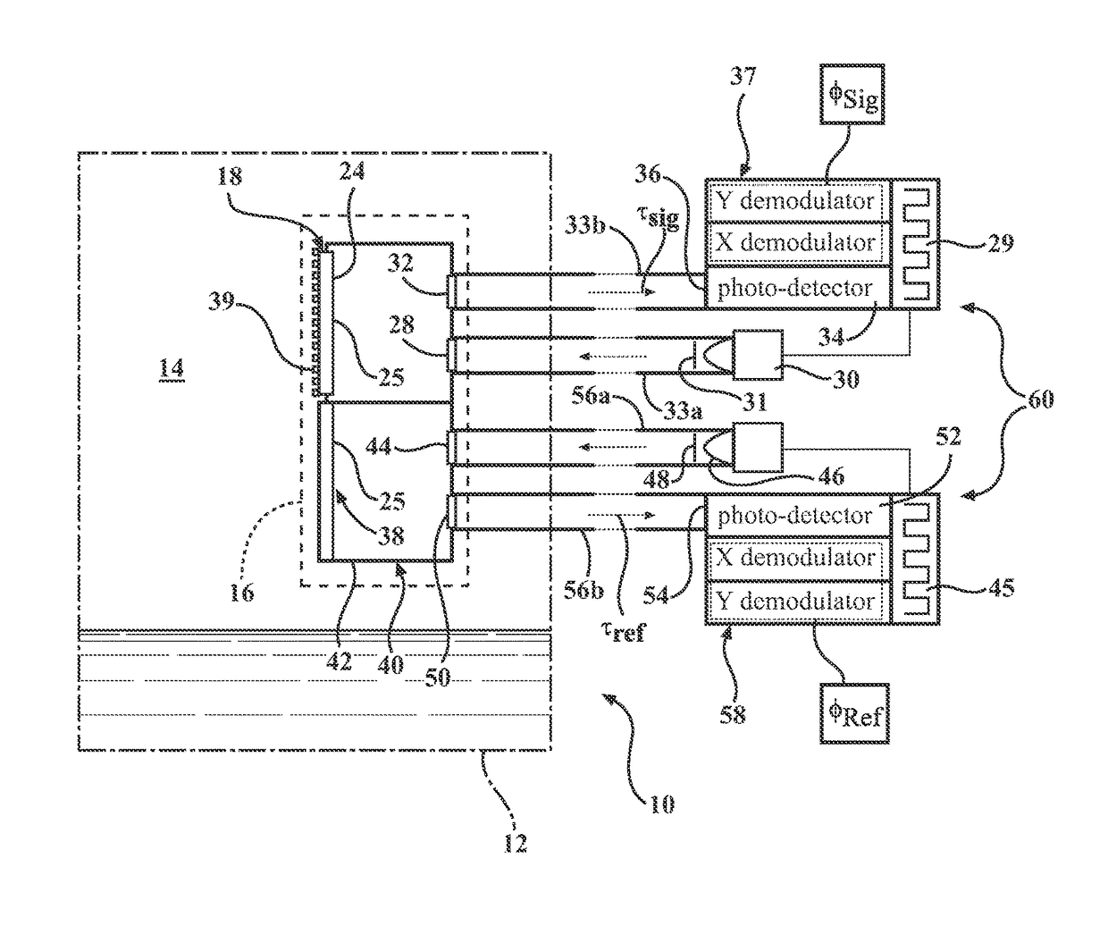
[0036]In accordance with an aspect of the invention, a sensor is provided for monitoring a sensed condition comprising oxygen number density, partial pressure, or concentration in which the effects of varying environmental conditions that could affect the accuracy of the sensed condition are reduced or minimized. In particular, the construction of the sensor includes selection of stable sensor materials in combination with a self-referencing construction for minimizing effects of variations within the measured environment, and within the...


PUM

PropertyMeasurementUnit
wavelengthaaaaaaaaaa
pressureaaaaaaaaaa

Abstract

An oxygen number density or concentration sensor including a sampling luminescent oxygen probe located in a fluid environment, and a gas impermeable enclosure located in the fluid environment and a reference luminescent oxygen probe located within the gas impermeable enclosure, wherein the sampling and reference luminescent oxygen probes are formed by an ideal PSP. A predetermined fixed oxygen number density or concentration is provided within a medium contained in the gas impermeable enclosure. A detector receives signals corresponding to luminescent emissions of the sampling and reference probes. A processor determines a number density or concentration of oxygen in the fluid environment from a signal generated at the sampling probe with reference to an oxygen number density or concentration dependent signal generated at the reference probe.

Description

CROSS REFERENCE TO RELATED APPLICATION[0001]This application claims the benefit of U.S. Provisional Patent Application Ser. No. 61 / 877,022, filed Sep. 12, 2013, entitled “MEASUREMENT OF OXYGEN”, the entire disclosure of which is incorporated by reference herein.FIELD OF THE INVENTION[0002]The present invention relates to monitoring a characteristic of fluids and, more particularly, to monitoring the number density, partial pressure or concentration of oxygen in a fluid.BACKGROUND OF THE INVENTION[0003]The number density, partial pressure or concentration of oxygen may be monitored in a gas or fluid, or in the space above a fluid in a tank or container for various reasons. For example, the concentration of oxygen may be monitored in a fuel tank as part of a fuel inerting system for avoiding or minimizing the possibility of combustion in the fuel tank.[0004]Fuel tank inerting systems have long been used in tactical aircraft, but are typically restricted to open-loop operation. While o...

Claims


Application Information

Patent Timeline
Patent Type & Authority Patents(United States)
IPC IPC(8): G01N21/64
CPCG01N21/643G01N2201/0627G01N2201/13G01N2021/6432G01N21/6408
Inventor CRAFTON, JIMMY W.FORLINES, ROBERT A.GOSS, LARRY P.PALLUCONI, STEPHEN J.WEBB, JESSICA R.ROGOSHCHENKOV, NIKOLAYMCMILLAN, GRANT R.
Owner INNOVATIVE SCI SOLUTIONS
Why Eureka
Try Eureka