
Steel rod and high strength wire having superior ductility and methods of production of same

a technology of ductility and high strength, which is applied in the direction of manufacturing tools, furnaces, heat treatment equipment, etc., can solve the problems of high cost, difficult refining of austenite grain size to a degree having an effect on the area reduction rate, and increase the cost of austenite, etc., to achieve superior ductility, high productivity, and high strength

Active Publication Date: 2010-05-27
NIPPON STEEL CORP
View PDF6 Cites 20 Cited by
  • Summary
  • Abstract
  • Description
  • Claims
  • Application Information

AI Technical Summary

Benefits of technology

[0010]The present invention was made in consideration of the above situation and has as its object to provide a steel rod superior in ductility for producing steel wire suitable for steel cord, sawing wire, and other applications and steel wire produced from the steel rod and to provide a method of producing the steel rod with high productivity and good yield in low cost.
[0018]By application of the present invention, high strength steel wire superior in ductility, in particular twistability, used in steel cord and sawing wires can be obtained with high productivity and good yield in low cost from high strength steel rod superior in ductility.

Problems solved by technology

However, these additive elements are expensive, so cause cost increase.
Further, according to verification by the inventors, it has been confirmed that with BN pinning, refining of austenite grain size to a degree having an effect on the area reduction rate is difficult.
This treatment causes high costs and simultaneously is liable to reduce the mechanical descaling performance.

Method used


Image

  • Steel rod and high strength wire having superior ductility and methods of production of same
  • Steel rod and high strength wire having superior ductility and methods of production of same
  • Steel rod and high strength wire having superior ductility and methods of production of same

Examples


example 1

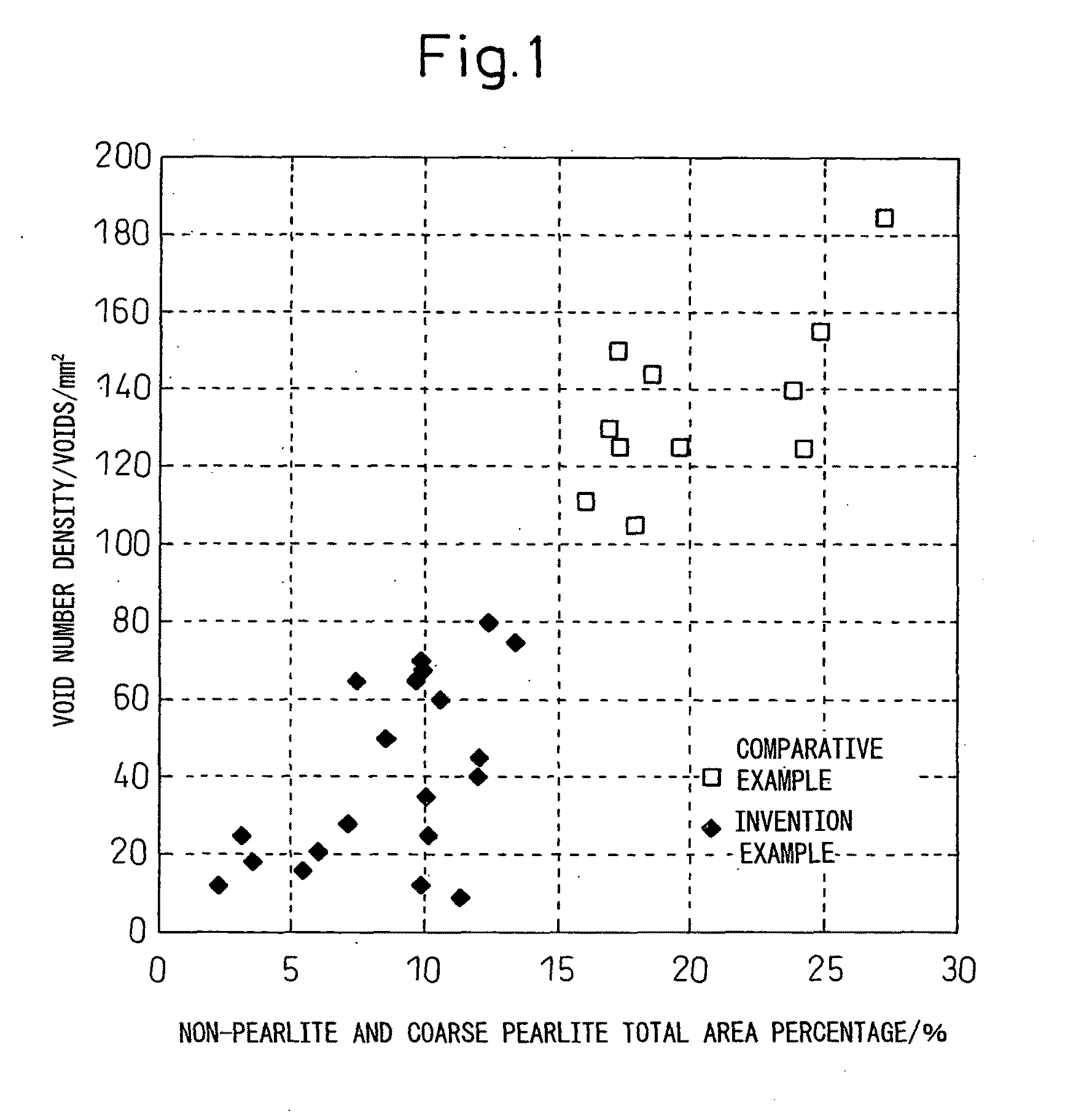
[0089]This is an example of the case using steel containing Mo. A billet using steel having each of the chemical components shown in Table 1 was heated, then hot rolled to rod having a diameter of 3 to 7 mm. The hot rolled rod was coiled in a ring shape at a predetermined temperature, then patented by the Stelmor treatment.

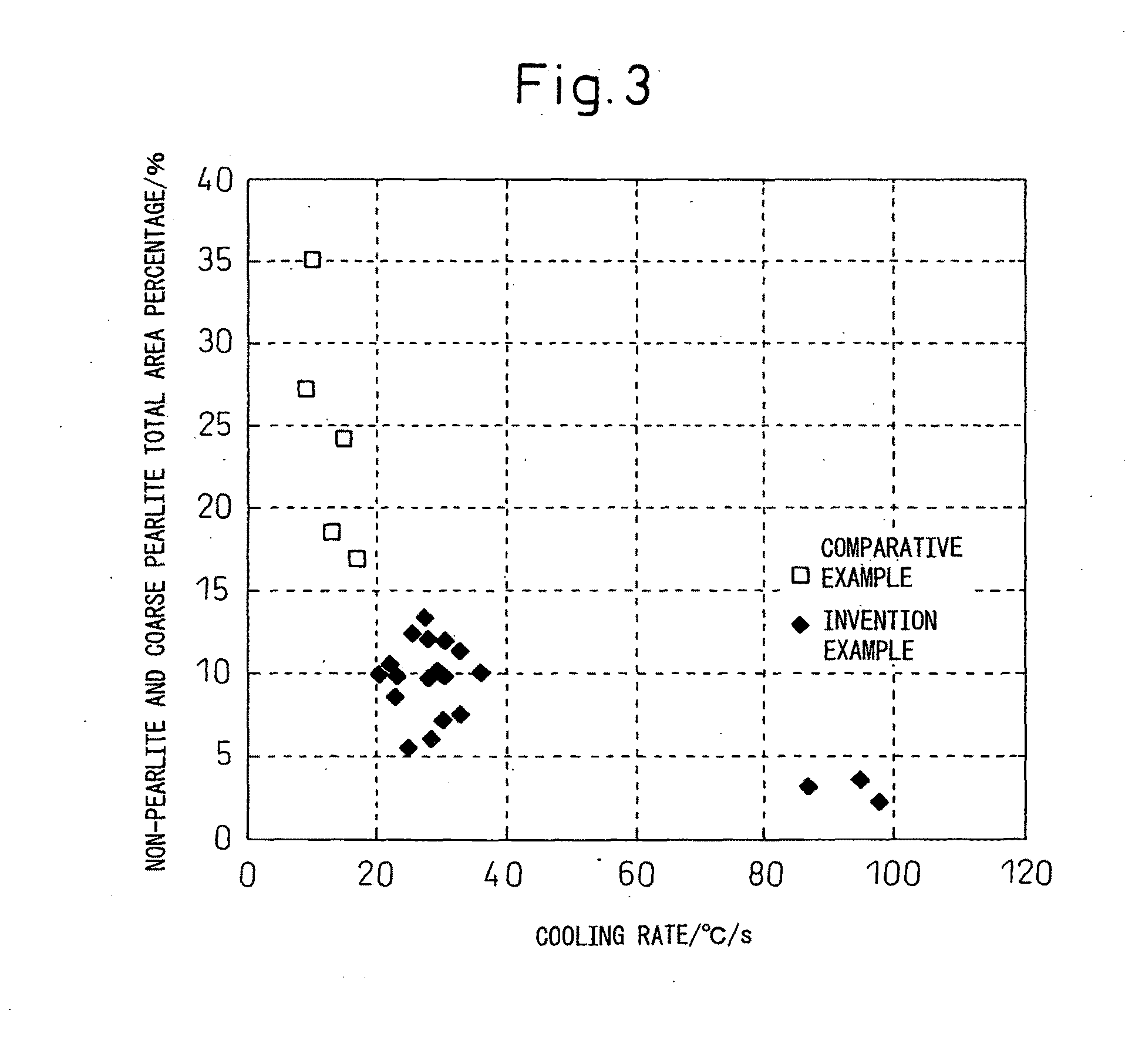
[0090]When patenting by the Stelmor treatment, the cooling rate at the overlapping part of the steel rod decreases, whereby the transformation temperature rises and coarse pearlite is easily formed. The cooling rate from 800° C. to 700° C. was obtained by measuring the temperature of the ring overlapping part using a non-contact type thermometer every 0.5 m on a Stelmor conveyor, then measuring the required time t for cooling from 800° C. to 700° C. The cooling rate was found to be (800-700) / t.

[0091]The patented rolled rod was cut to samples which were subjected to tensile tests. Also, to measure the area percentages of the non-pearlite structures and coarse pearl...

example 2

[0112]This is an example of the case using steel containing Mo. A billet using steel having each of the chemical components shown in Table 3 was used in the same way as in Example 1 to make a steel rod having a diameter of 5.5 mm, this steel rod was coiled in a ring shape at a predetermined temperature, then was patented by Stelmor treatment or patented by immersion in molten salt (DLP).

[0113]Samples were taken from the patented rolled rod in the same way as in Example 1 and subjected to a tensile test and observed by SEM.

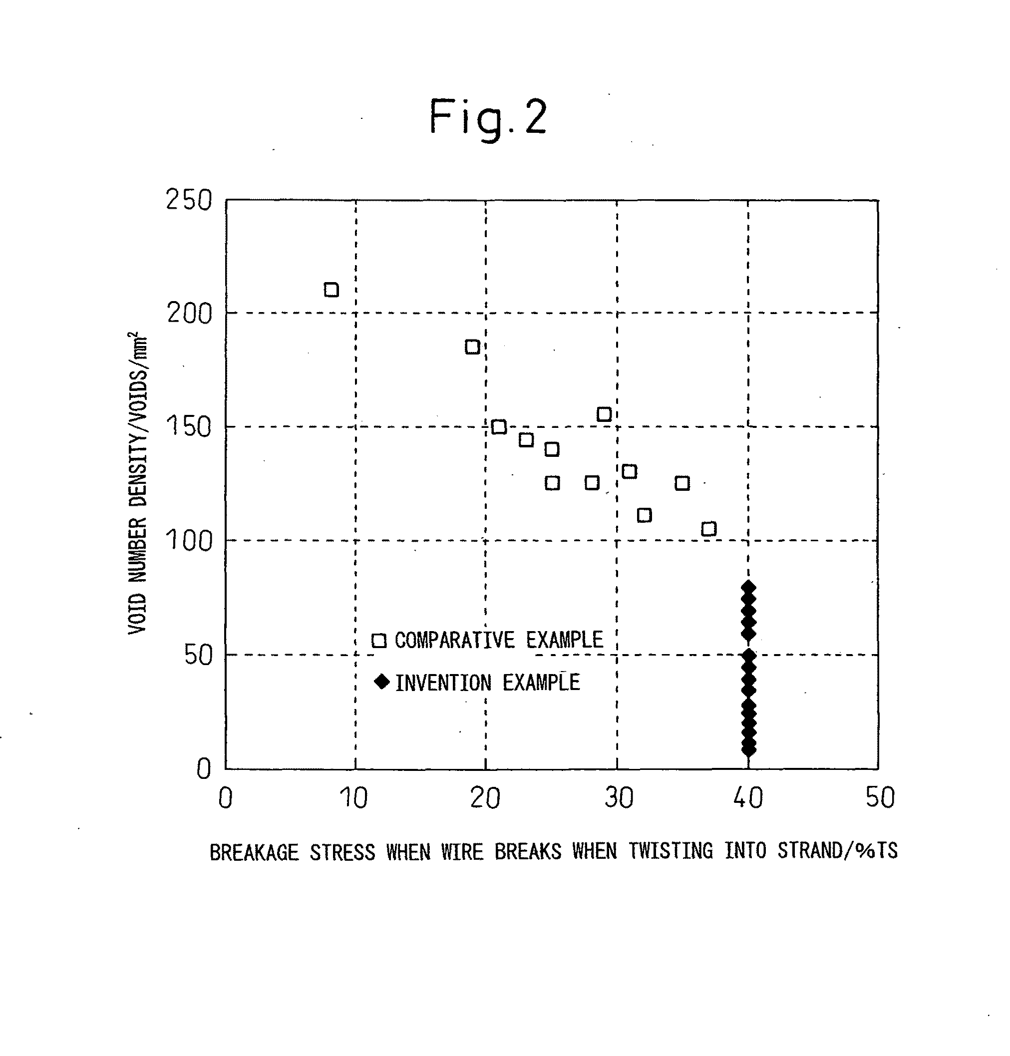
[0114]Next, to obtain the drawing characteristics of the steel rod, the material was drawn in the same way as in Example 1 to obtain a steel wire having a final drawing diameter. Samples were extracted from the obtained steel wire and subjected to a tensile test and measured for number density of voids.

[0115]Further, the prepared steel wire was used and twisted in the same way as in Example 1 and examined for the occurrence of breakage of wire and the breakage stre...

example 3

[0119]This is an example of the case of mainly using steel containing W and partially using steel containing both W and Mo. A billet using steel having each of the chemical components shown in Table 5 was used in the same way as in Example 1 to make a steel rod having a diameter of 4 to 6 mm, the steel rod was coiled in a ring-shape at a predetermined temperature, then this was patented by a Stelmor treatment.

[0120]Samples were taken from the patented rolled steel rod in the same way as Example 1 and subjected to a tensile test and observed by SEM.

[0121]Next, to obtain the drawing characteristics of the steel rod, the rod was drawn in the same way as in Example 1 to obtain a steel wire having a final drawing diameter. Samples were extracted from the obtained steel wire and subjected to a tensile test and measured for number density of voids.

[0122]Further, the prepared steel wire was used and twisted in the same way as in Example 1 and examined for the occurrence of breakage of wire ...


PUM

PropertyMeasurementUnit
Temperatureaaaaaaaaaa

Abstract

The present invention inexpensively provides with high productivity and good yield a steel rod superior in drawability and a steel wire superior in twistability using the same as a material, that is, draws a high strength steel rod superior in ductility where the chemical components contain C: 0.80 to 1.20%, Si: 0.1 to 1.5%, Mn: 0.1 to 1.0%, Al: 0.01% or less, Ti: 0.01% or less, one or both of W: 0.005 to 0.2% and Mo: 0.003 to 0.2%, N: 10 to 30 ppm, B: 4 to 30 ppm (of which, solute B is 3 ppm or more), and O: 10 to 40 ppm, which has a balance of Fe and unavoidable impurities, has an area percentage of pearlite structures of 97% or more, has a balance of non-pearlite structures, and has a total of the area percentage of the non-pearlite structures and the area percentage of the coarse pearlite structures of 15% or less, to obtain high strength steel wire superior in ductility having a tensile strength of 3600 MPa or more and a number density of voids of lengths of 5 μm or more at the center of 100 / mm2 or less

Description

TECHNICAL FIELD[0001]The present invention relates to a steel rod superior in ductility, a high strength steel wire superior in ductility and twistability produced using the steel rod, and methods of production of the same. More specifically, it relates to a rolled steel rod superior in ductility for obtaining steel wire suitable for steel cord used as reinforcement material in for example automobile radial tires, belts for industrial use, and the like, further a sawing wire, and other applications, a high strength steel wire mentioned above obtained from the rolled rod, and methods of production of the same.BACKGROUND ART[0002]Steel wire for steel cord used as reinforcement material for automobile radial tires, various belts, and hoses or steel wire for sawing wire is generally produced by hot rolling a steel billet, then controllably cooling it to obtain a steel rod (rolled rod) of a diameter of 4 to 6 mm, and drawing this rolled rod to a diameter 0.15 to 0.40 mm ultrafine wire. F...

Claims


Application Information

Patent Timeline
IPC IPC(8): C21D9/00C22C38/00
CPCC21D8/065C22C38/04C22C38/02C22C38/001C21D9/525B21C1/003C21D6/004C21D6/005C21D6/007C21D6/008C21D2211/009C22C38/002C22C38/06C22C38/08C22C38/10C22C38/12C22C38/14C22C38/16C22C38/20C22C38/22C22C38/26C22C38/28C22C38/30C22C38/32C22C38/54D07B1/066D07B2205/3035D07B2205/3057
Inventor YAMASASKI, SHINGONISHIDA, SEIKI
Owner NIPPON STEEL CORP
Learn More