Article transfer device and article transport facility

a technology of transfer device and article, which is applied in the direction of electric motor control, transportation and packaging, instruments, etc., can solve the problems of increasing error between reducing and increasing the target rotational speed and the actual rotational speed of the electric motor

Active Publication Date: 2017-08-01
DAIFUKU CO LTD
View PDF4 Cites 16 Cited by
  • Summary
  • Abstract
  • Description
  • Claims
  • Application Information

AI Technical Summary

Benefits of technology

[0007]Subsequently, when the contact member collides with the article, the extra load due to the collision will be added to the contact member. This causes the actual rotational speed of the electric motor to decrease, which in turn causes the error between the target rotational speed and the actual rotational speed of the electric motor to increase. Furthermore, with the article transfer device described in Patent Document 1, the target rotational speed of the electric motor is increased at the moment of, or after, the contact member coming into contact with the article; thus, the error between the target rotational speed and the actual rotational speed of the electric motor becomes even greater. As a result, in response to the rapid increase in the error, command values are issued to the electric motor that would cause the electric motor (which has been slowed down by the collision between the contact member and the article) to accelerate very rapidly.
[0008]The contact member as well as the article is accelerated rapidly with the rapid increase in the rotational speed of the electric motor. As a result, the actual rotational speed of the electric motor approaches the target rotational speed, which reduces the difference between the two speeds. Thus, in response to the decreased error, new command values which would cause the electric motor to decelerate are then given to the electric motor.
[0009]When the electric motor decelerates, the moving speed of the contact member which is operatively connected with the electric motor also decreases. However, because of its inertia, the moving speed of the article is still the same as the speed at the time the electric motor accelerated rapidly. Therefore, the moving speed of the article ends up being greater than the moving speed of the contact member. As a result, the contact member and the article are moved apart from each other, which reduces the load on the electric motor.
[0018]With the arrangement describe above, when the rotational speed of the electric motor is decreased when the external force applied condition is satisfied while performing the first control, the actuation controller performs a second control for providing the electric motor with a command value that allows the actual rotational speed to be equal to, and to fall below, the first target rotational speed at a time of the external force applied condition becoming satisfied. In other words, even if the rotational speed of the electric motor is decreased as a result of the fact that the external force applied condition is satisfied, the electric motor would not receive any commands that would cause it to operate at speeds greater than the first target rotational speed at a time of the external force applied condition becoming satisfied, while the second control is performed after performing the first control. As a result, while the second control is performed, any large changes in the actual rotational speed of the electric motor would be suppressed. Therefore, the problem with the conventional system that large changes or fluctuations in the actual rotational speed of the electric motor are repeated and thus collisions and separations between the contact member and the article are repeated can be alleviated.

Problems solved by technology

This causes the actual rotational speed of the electric motor to decrease, which in turn causes the error between the target rotational speed and the actual rotational speed of the electric motor to increase.
Furthermore, with the article transfer device described in Patent Document 1, the target rotational speed of the electric motor is increased at the moment of, or after, the contact member coming into contact with the article; thus, the error between the target rotational speed and the actual rotational speed of the electric motor becomes even greater.

Method used


Image

  • Article transfer device and article transport facility
  • Article transfer device and article transport facility
  • Article transfer device and article transport facility

Examples


first embodiment

[0036]The article transfer device in accordance with the first embodiment is described with reference to the drawings.

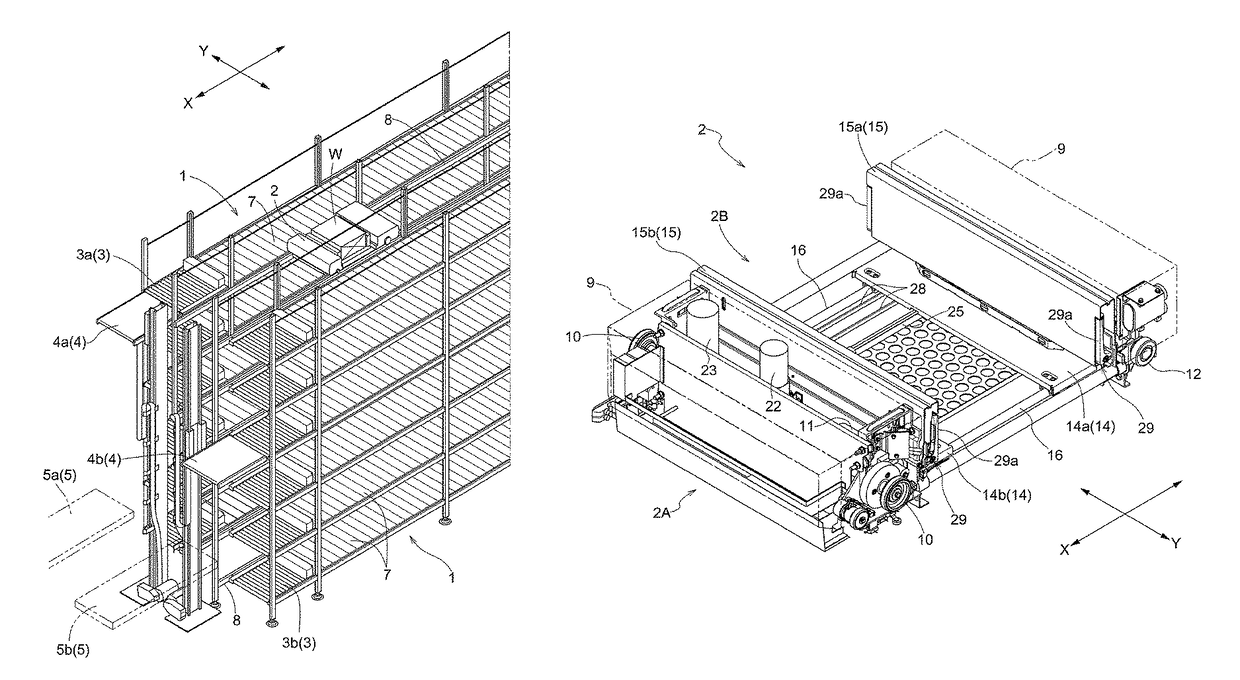
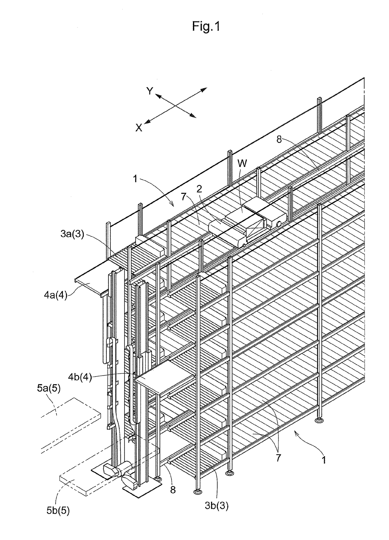
[0037]FIG. 1 is a perspective view of an article transport facility which incorporates an article transfer device 2B. As shown in FIG. 1, the article transport facility has article support portions 1 each of which is configured to support articles, and article transports 2 each of which is capable of moving along its travel path. Each article transport 2 is configured to be capable of delivering articles W, one at a time, to either of the article support portions 1 and receiving articles W, one at a time, from either of the article support portions 1 by moving the article W along a transfer direction by means of its article transfer device 2B at predetermined or preset locations along the travel path.

[0038]As shown in FIG. 1, the article support portions 1 are used to store articles W. Travel rails 8 which define the travel path generally extends linearly along a dir...

fourth embodiment

[0115] In the fourth embodiment described above, the case in which an article W being transferred by the hooks 29a collides with a step “d” is described as an example of an external force applied condition (that an external force that causes a decrease in the rotational speed of the projecting and retracting motor 22 is applied) being satisfied. The external force applied condition may also be satisfied when the article W transferred by the hooks 29a collides with other objects. For example, the external force applied condition may be satisfied when the article W being transferred by the hooks 29a comes into contact with components of the article transport facility described above (for example, an article support portion 1, a relay conveyor 3, a load support platform 48, or the component parts of the article transfer device 2B, 2C itself, etc.).

[0116] Any arrangement and structure disclosed in any one embodiment (including the alternative embodiments, which is true of any embodiment...


PUM


Abstract

When an external force applied condition that an external force that causes a decrease in a rotational speed of an electric motor is applied to the contact member moved by the electric motor is satisfied while the actuation controller is performing a first control for continuously performing a process of providing the electric motor with a command value that depends on an error between an actual rotational speed of the electric motor and a first target rotational speed so as to cause the actual rotational speed to approach the first target rotational speed, then the actuation controller, subsequent to the first control, performs a second control for providing the electric motor with a command value that allows the actual rotational speed of the motor to be equal to, and to fall below, the first target rotational speed at a time of the external force applied condition becoming satisfied.

Description

CROSS-REFERENCE TO RELATED APPLICATION[0001]This application claims priority to Japanese Patent Application No. 2015-226008 filed Nov. 18, 2015, the disclosure of which is hereby incorporated in its entirety by reference.FIELD OF THE INVENTION[0002]The present invention relates to an article transfer device configured to move an article along a transfer direction and an article transport facility having such an article transfer device.BACKGROUND[0003]JP Publication of Application No. 2004-203546 (Patent Document 1) describes an article transfer device for moving articles along a transfer direction. More specifically, the article transfer device described in Patent Document 1 includes a contact member that contacts an article and moves the article by moving along the transfer direction, an actuating mechanism which includes an electric motor for moving the contact member along the transfer direction, and an actuation controller which controls the action of the actuating mechanism. An...

Claims


Application Information

Patent Timeline
Patent Type & Authority Patents(United States)
IPC IPC(8): G06F7/00B65G1/04B65G1/06H02P31/00
CPCB65G1/0492B65G1/0435B65G1/06H02P31/00B65G2203/0266B65G1/04B65G35/00B65G1/0414B65G1/065
Inventor KOIDE, HIROYUKI
Owner DAIFUKU CO LTD
Why Eureka
Try Eureka