Wireless communication systems for underground pipe inspection

a communication system and underground pipe technology, applied in the field of pipe leakage detection, can solve the problems of limited scanning range, limited sensor mobility, and traditional wired communication systems that do not work well, and achieve the effect of energy-efficient communication and prolonging the network lifetim

Active Publication Date: 2017-08-01
KING FAHD UNIVERSITY OF PETROLEUM AND MINERALS +1
View PDF6 Cites 28 Cited by
  • Summary
  • Abstract
  • Description
  • Claims
  • Application Information

AI Technical Summary

Benefits of technology

[0014]Wireless sensor networks are energy-constrained, especially with underground in-pipe sensor nodes powered by batteries. The present invention also provides methods and communication protocols to enable energy-efficient communications and prolong the network lifetime.

Problems solved by technology

There are several critical challenges on the development of a communication system for in-pipe inspection.
First, traditional wired communication systems [6] do not work well.
Wired systems have several drawbacks, such as limited scanning range, limited sensor mobility, and system failure due to wire damage.
Second, for wireless communication systems, signals need to travel through different media, including water, plastic, soil, and air, to reach aboveground.
Third, the battery-based energy supply of the in-pipe sensor nodes is limited.
However this wireless communication method may not work well with water pipelines due to the high attenuation of radio waves in water.
However, sensors are affixed to the outside of the pipeline, making it difficult to detect small leaks or damage to the pipeline.
However sensors in those systems are deployed at some fixed check points inside the pipe, which is unfeasible for performing sensing very close to a leak.
However, the designers make no explanation of how to transmit the information from an underground pipeline to aboveground devices.
However, two of the major challenges associated with acoustic communication systems are limited transmission bandwidth and high power consumption.
These drawbacks make acoustic communication systems unsuitable for monitoring long pipelines with different pipe geometries.
However, in view of the short range of communications between two neighboring magnetic induction units or coils, it is impossible to perform large-scale deployment of such units or coils on long underground pipelines.
However, this wireless communication method is unsuitable for in-pipe inspection systems due to deployment challenges.

Method used


Image

  • Wireless communication systems for underground pipe inspection
  • Wireless communication systems for underground pipe inspection

Examples


Embodiment Construction

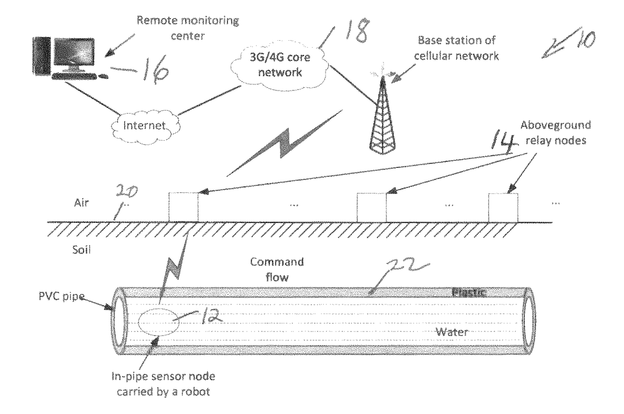
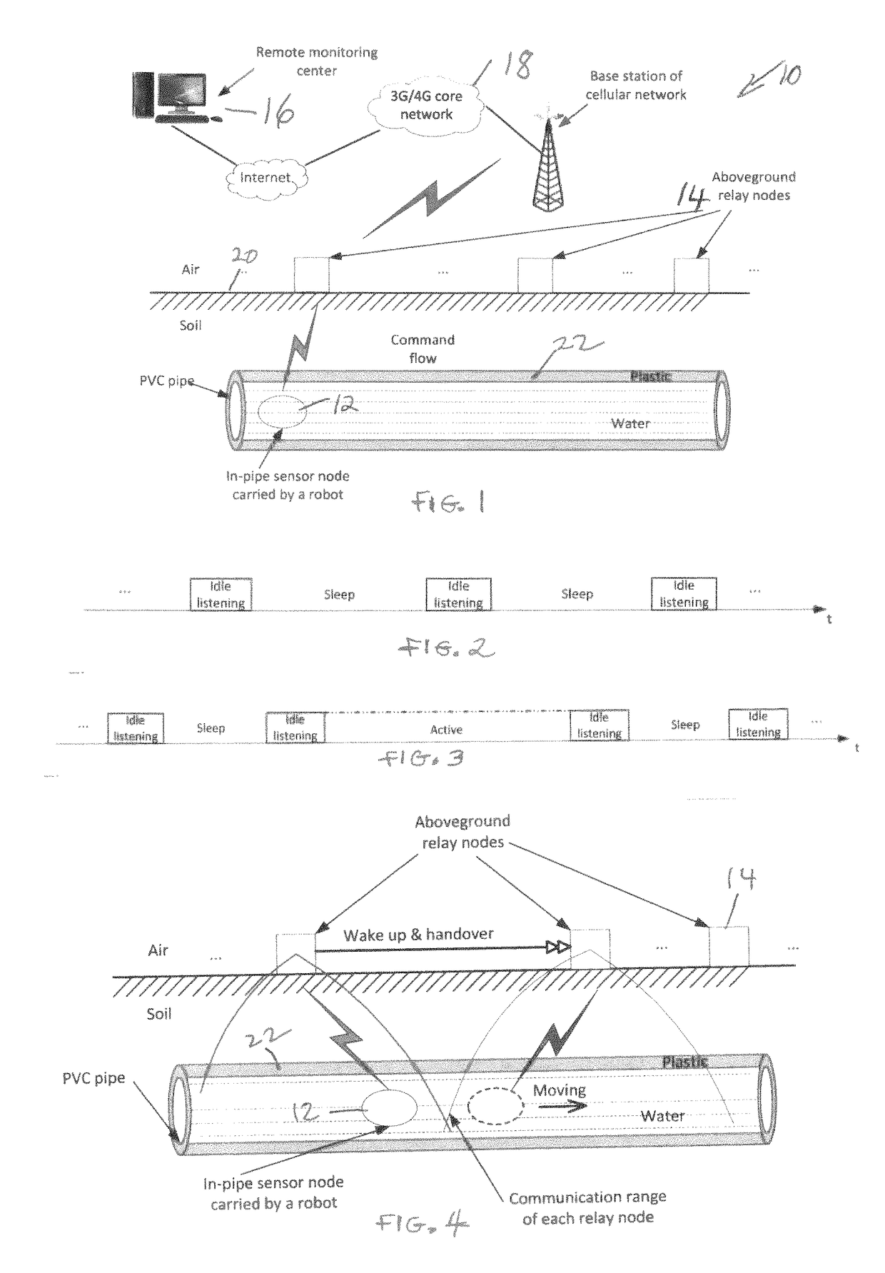
[0020]The present invention provides a wireless communication system for underground in-pipe inspection. As shown in FIG. 1, a wireless communication system 10 for underground pipeline inspection comprises mobile in-pipe sensor node 12, aboveground relay nodes 14, a remote monitoring center 16, and a mobile communication network 18 from a third-party service provider.

[0021]Each sensor node 12 is carried by a robot, and can move back and forth inside the pipeline. Each sensor node 12 is equipped with different types of sensors, such as acoustic or pressure sensors to detect a leak. Each sensor node 12 may include a microcontroller for robot control and data processing. Each sensor node 12 also may include a low-frequency radio transceiver for communication with the relay nodes. Additionally, each sensor node preferably also includes an accelerometer and a timer to help localize the position of the sensor node.

[0022]The relay nodes 14 are deployed on the soil surface 20 along the pipe...


PUM


Abstract

Wireless communication system for underground pipeline inspection. The system includes a plurality of sensor nodes moved by robots within the pipeline and each sensor node includes a radio transceiver. A plurality of spaced apart, above ground relay nodes are deployed along the pipeline, each relay node including a radio transceiver for communication with the sensor nodes. A remote monitoring center is provided in communication with the relay nodes, whereby a leak detected by a sensor node is communicated to the remote monitoring center. Each sensor node may further include a microcontroller, an accelerometer and a timer.

Description

[0001]This application claims priority to U.S. Provisional Application Ser. No. 61 / 918,791 filed on Dec. 20, 2013, the contents of which are incorporated herein by reference.BACKGROUND OF THE INVENTION[0002]This invention relates to pipeline leakage detection and more particularly to a wireless communication system for transmitting leakage information to a remote location.[0003]Water leakage can reach 30% on average of the water transported across the water distribution networks [1, 2]. Many different techniques have been developed to detect leaks, either from the inside [3, 4] or from the outside of pipes [5]. Studies [3] have shown that compared with outside-of-the-pipe inspection, in-pipe inspection is much more accurate. In-pipe inspections are less sensitive to random events and external noise as well as less subjective to the operator's experience.[0004]Communication functions are extremely important for an in-pipe inspection system to provide effective leak detection. For acc...

Claims


Application Information

Patent Timeline
Patent Type & Authority Patents(United States)
IPC IPC(8): G08C17/00G01M3/18G01M3/24H04W36/18G08B21/20H04W52/02H04W84/12
CPCG08B21/20G01M3/18G01M3/243H04W36/18H04W52/0203H04W84/12Y02B60/50Y02D30/70
Inventor WU, DALEIYOUCEF-TOUMI, KAMALMEKID, SAMIRBEN-MANSOUR, RACHED
Owner KING FAHD UNIVERSITY OF PETROLEUM AND MINERALS
Why Eureka
Try Eureka