Mobile X-ray unit

a x-ray unit and mobile technology, applied in the field of mobile x-ray units, can solve the problems of 1 billion euros in medical treatment expenses, long waiting lists, and poor control, and achieve the effect of reducing the size of the x-ray applicator in the whol

Active Publication Date: 2017-08-08
NUCLETRON OPERATIONS
View PDF13 Cites 8 Cited by
  • Summary
  • Abstract
  • Description
  • Claims
  • Application Information

AI Technical Summary

Benefits of technology

[0010]It may be advantageous to provide a phantom-based dosimetry system so as to provide an efficient method of determining the radiation delivered from the mobile X-ray unit for quality and safety control.
[0034]It may be advantageous to provide an independent mechanism for detecting the presence of an X-ray beam. In some embodiments, the X-ray unit includes a primary timer which may set a time for the high voltage supply to deliver a predetermined radiation dose. The radiation detector disposed inside the outer housing of the X-ray applicator may be part of a secondary timer circuit adapted to shut down the high voltage supply when the predetermined radiation dose has been delivered. In this way radiation safety control may be improved.

Problems solved by technology

Increased exposure to the sun without skin protection and a decreased ozone layer are regarded as the main causes of this increase—a problem estimated to be costing over 1 billion Euros in annual medical treatment expenses.
Surgery, may, however, have certain drawbacks, such as, for example, long waiting lists, complications related to post-treatment care, and risk of infection.
For example, there may be poor control resulting in difficulty delineating between the X-ray beam emitted from the X-ray tube and a treated region on the patient.

Method used


Image

  • Mobile X-ray unit
  • Mobile X-ray unit
  • Mobile X-ray unit

Examples


first embodiment

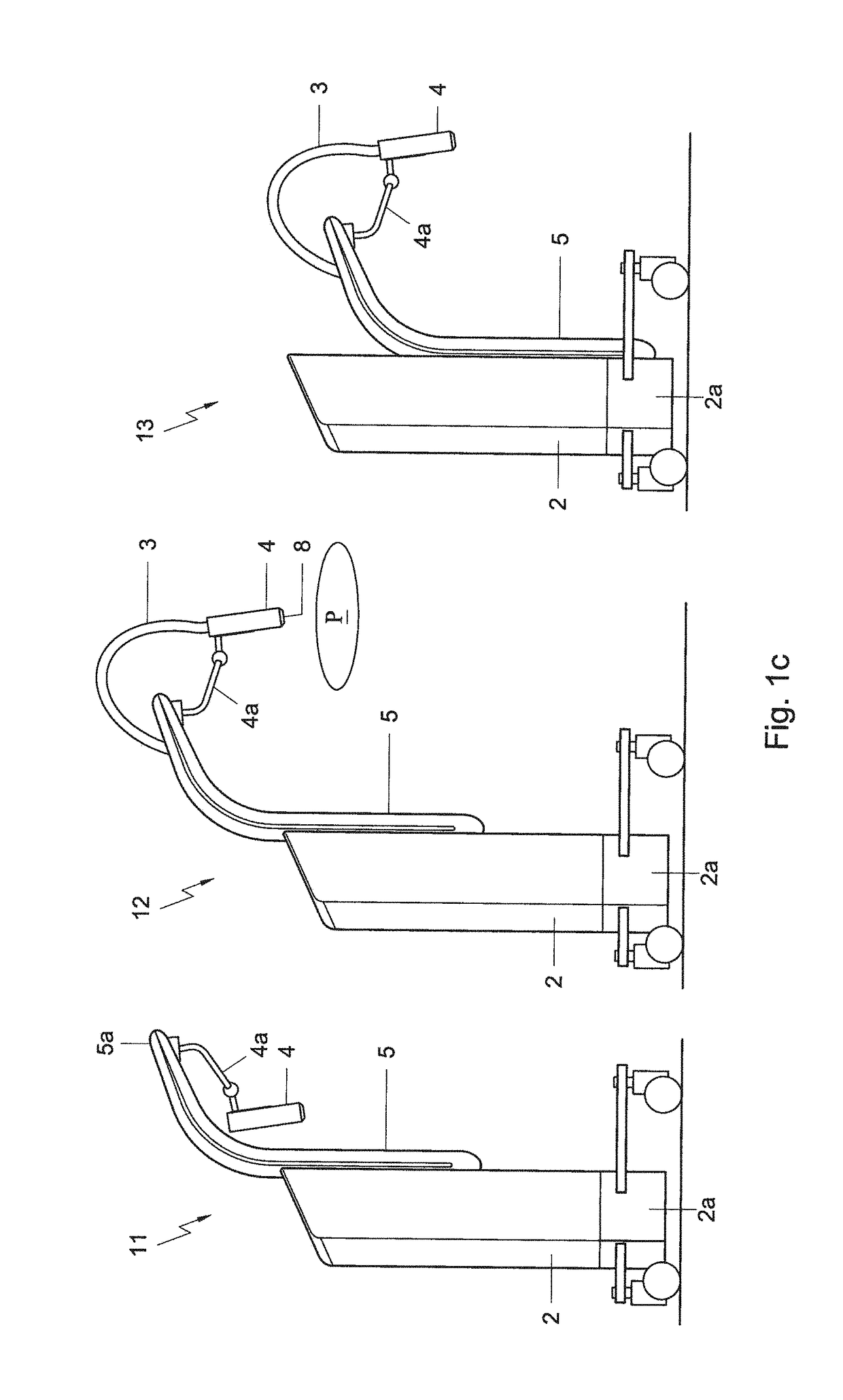
[0046]FIG. 4a presents a cross-sectional view of an X-ray applicator of the mobile X-ray unit having an indicator, according to the present disclosure.

second embodiment

[0047]FIG. 4b presents a cross-sectional view of an X-ray applicator of the mobile X-ray unit having an indicator, according to the present disclosure.

third embodiment

[0048]FIG. 4c presents a cross-sectional view of an X-ray applicator of the mobile X-ray unit having an indicator, according to the present disclosure.

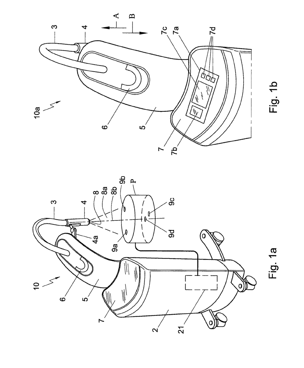
[0049]FIG. 5a presents a schematic view of a phantom-based dosimetry system, according to embodiments of the present disclosure.

[0050]FIG. 5b presents a cross-section of the phantom-based dosimetry system of FIG. 5a, according to embodiments of the present disclosure.

[0051]FIG. 6 presents an end view of an X-ray tube, according to embodiments of the present disclosure.

[0052]FIG. 6, E-E presents a cross-section along line VII-E of the X-ray tube of FIG. 6, according to embodiments of the present disclosure.

[0053]FIG. 6, F-F presents a cross-section along line VII-F of the X-ray tube of FIG. 6, according to embodiments of the present disclosure.

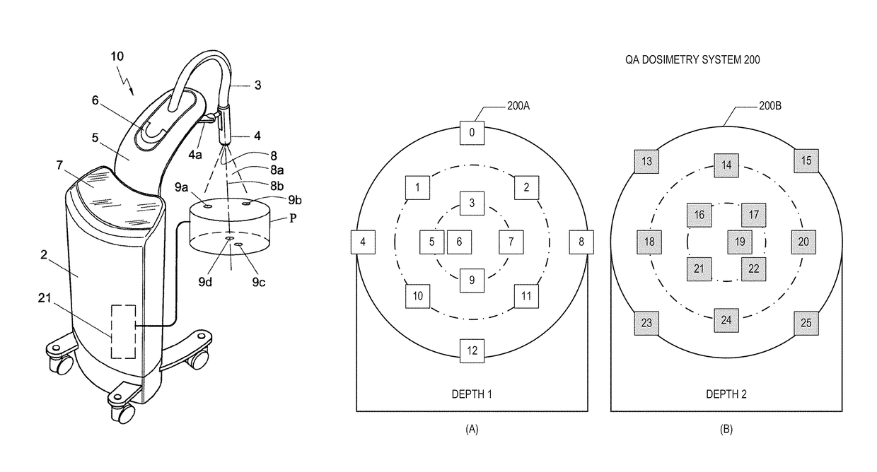
[0054]FIG. 7 presents cross-sectional views of an exemplary dosimetry system for quality assurance, according to embodiments of the present disclosure.

[0055]FIG. 8 presents a flow chart illustrat...


PUM


Abstract

One embodiment of the present disclosure is directed to a mobile X-ray unit. The mobile X-ray unit may include an X-ray applicator for emitting an X-ray beam for irradiating an object. The mobile X-ray unit may further include a phantom-based dosimetry system configured to perform a dosimetry check of the X-ray beam. The phantom-based dosimetry system may include two sets of dose meters, each set being positioned on a surface at a distinct depth. The mobile X-ray unit may also include a dosimetry control unit configured to receive measurements from the two sets of dose meters and determine whether the dosimetry check is passed based on the measurements.

Description

[0001]This application is a continuation-in-part of copending U.S. patent application Ser. No. 13 / 335,830, filed Dec. 22, 2011, which claims the benefit of priority based on U.S. Provisional Patent Application No. 61 / 426,925, filed Dec. 23, 2010, and Netherlands Patent Application No. 2005899, filed Dec. 22, 2010. All of the priority documents listed above are incorporated herein by reference.DESCRIPTION OF THE INVENTION[0002]Field of the Invention[0003]The invention relates generally to a mobile X-ray unit. The present disclosure further relates to a method for dosimetry control of an X-ray beam emitted from the mobile X-ray unit.[0004]Background of the Invention[0005]The incidence rate of skin cancer has substantially increased in the last decade of the 20th century. It is appreciated that over 1.3 million new skin cancers are diagnosed annually, which is increasing at a rate of about 5% per year. Increased exposure to the sun without skin protection and a decreased ozone layer ar...

Claims


Application Information

Patent Timeline
Patent Type & Authority Patents(United States)
IPC IPC(8): A61B6/00A61N5/10G01T1/02A61B5/107
CPCA61B6/583A61B6/488A61B6/582A61B6/585A61N5/1071G01T1/02A61B5/1075A61B6/42A61B6/44A61B6/4423A61B6/542A61B6/58A61N5/1048A61N2005/1076A61N2005/1091G01N2223/3035
Inventor VAN DER VEEN, JOHANNES SIMONWOUDSTRA, BASHENNING, JOHAN
Owner NUCLETRON OPERATIONS
Why Eureka
Try Eureka