Bone graft injection methods

a bone graft and injection method technology, applied in dental tools, diagnostics, dental tools, etc., can solve the problems of bone augmentation procedures that are often difficult to perform surgically, perforation of the membrane, and the replacement of the maxillary teeth, so as to reduce the risk of perforation, reduce the risk of infection, and enhance the maxillary alveolar ridge.

Inactive Publication Date: 2017-08-15
MAXILLENT
View PDF228 Cites 7 Cited by
  • Summary
  • Abstract
  • Description
  • Claims
  • Application Information

AI Technical Summary

Benefits of technology

[0007]Some embodiments of the present invention provide a surgical tool for use in conjunction with minimally-invasive sinus lift techniques for augmenting the maxillary alveolar ridge while reducing the risk of perforating the Schneiderian membrane and of infection. The surgical tool is configured to inject, through a bore (osteotomy) and into a sinus cavity, a solid-liquid composition of bone graft particles and a physiological liquid solution, and to drain the physiological liquid solution through the same bore, leaving the bone graft particles in the cavity. Typically, a filter of the surgical tool is used to inhibit passage of bone graft particles from the cavity. Typically, hydraulic pressure is equally applied on the Schneiderian membrane by the solid-liquid composition throughout the injection of the solid-liquid composition. Such uniform hydraulic pressure prevents bone graft particles from applying local or uneven pressure on the Schneiderian membrane, and thus reduces the risk of perforation. The surgeon further screws an implant into the bone graft material in the cavity, either during the same procedure or after bone grows into the bone graft material. After bone grows into the bone graft material, a dental appliance, such as a crown, is coupled to the implant.

Problems solved by technology

Replacement of the maxillary teeth is often a challenging surgical procedure when the remaining maxillary bone has insufficient height to support the implant.
Bone augmentation procedures are often surgically difficult to perform, and are associated with complications, including infection of the maxillary sinus.
This is often difficult, because of the delicacy of the membrane, and the restricted access afforded by the closed approach.
This technique is manually demanding, and it may cause application of unequal stresses to the membrane, which may result in perforation of the membrane.

Method used


Image

  • Bone graft injection methods
  • Bone graft injection methods
  • Bone graft injection methods

Examples


Embodiment Construction

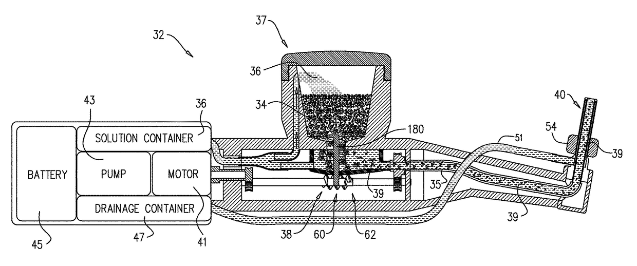
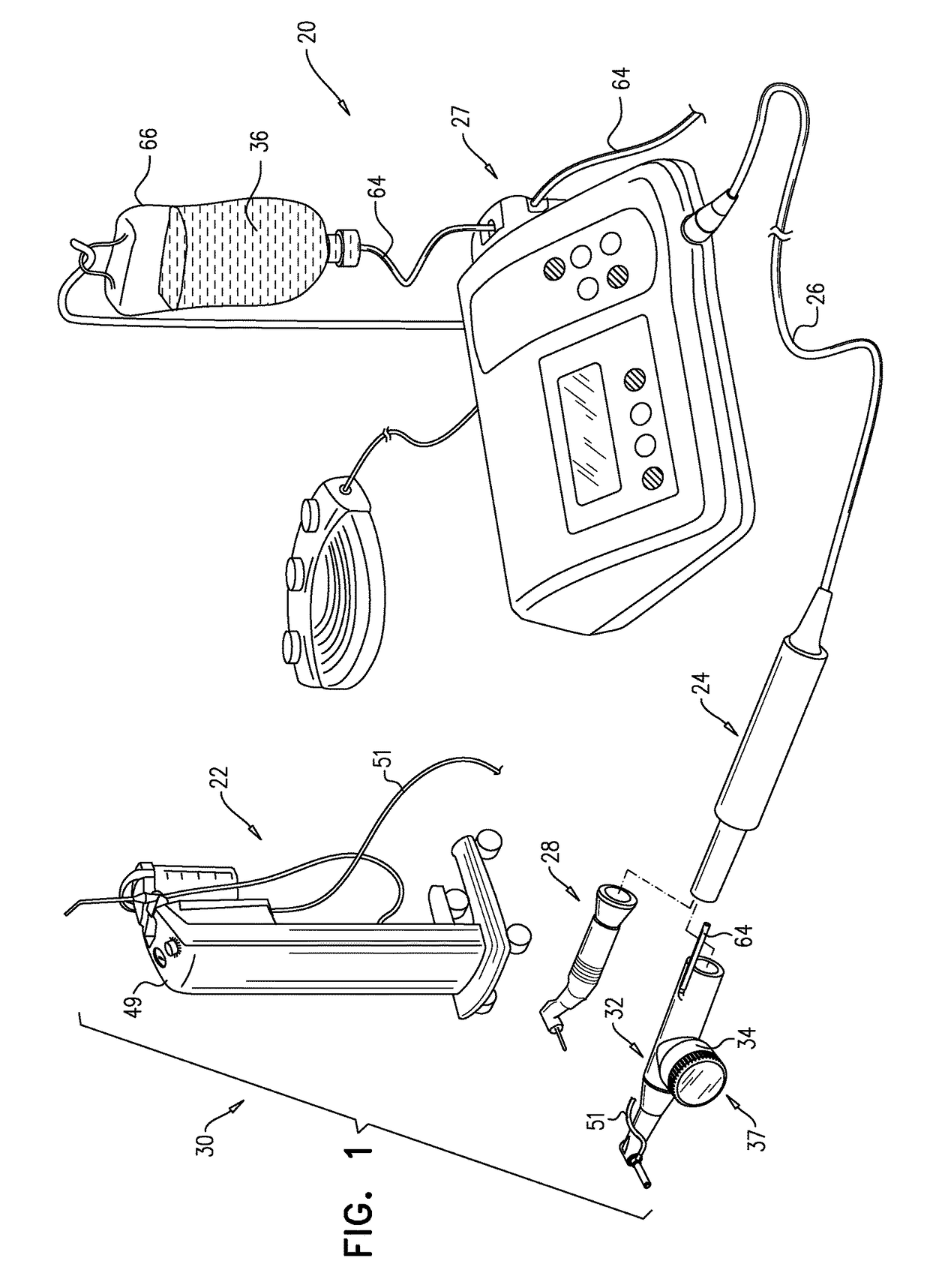
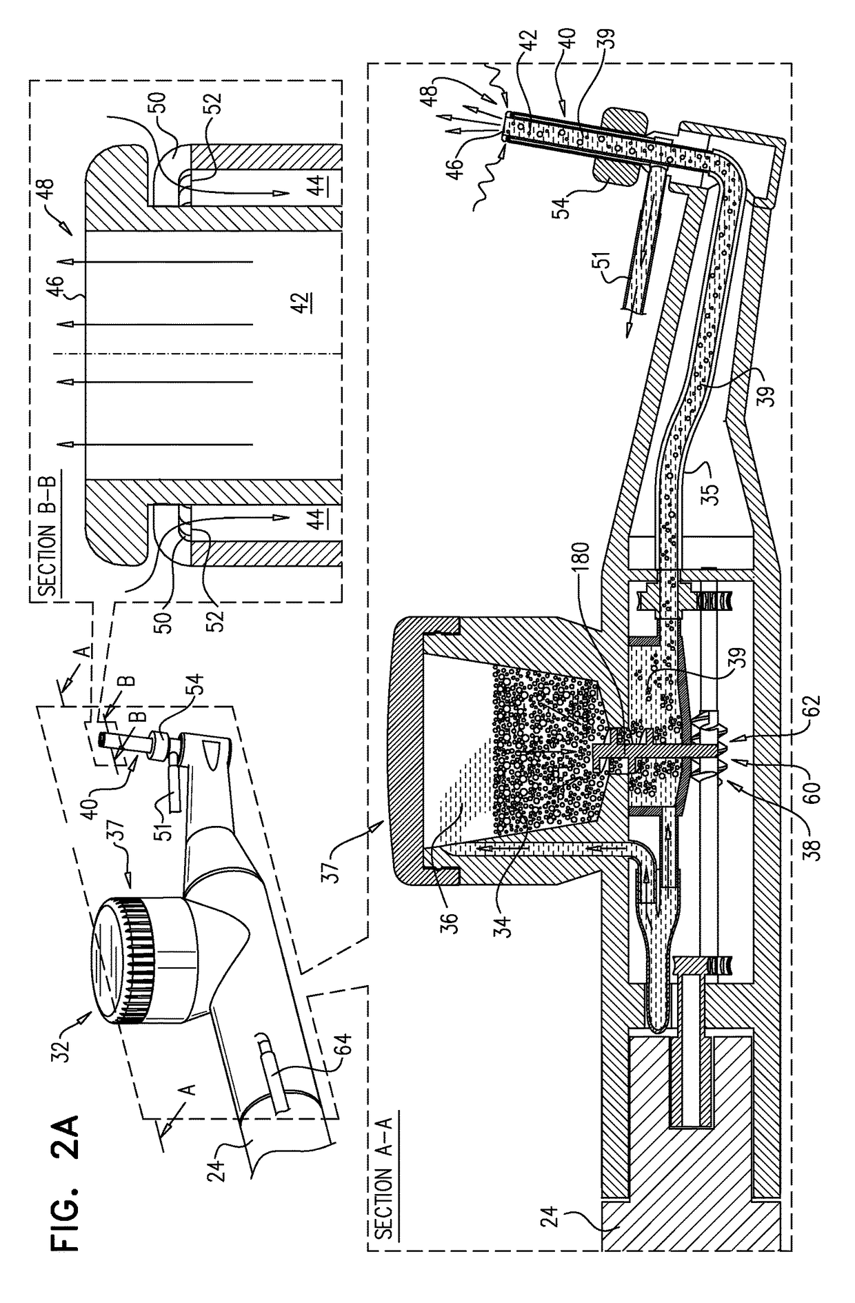
[0229]FIG. 1 is a schematic illustration of a surgical tool 20 for the insertion of bone graft particles into a cavity, in accordance with an application of the present invention. For some applications, surgical tool 20 is configured as an oral surgical tool. Surgical tool 20 may comprise one or more of the following components:[0230]a handheld motor 24, as is known in the art, which is typically connected to external control unit 22 by a cord 26;[0231]an external control unit 22, which optionally comprises a conventional surgical implant external control unit; typically, external control unit 22 comprises a power supply, electronics, and a user interface for controlling handheld motor 24, as is known in the art; for some application, external control unit 22 comprises a pump 27, such as a peristaltic pump, as is known in the art;[0232]one or more conventional drilling handpieces 28; and / or[0233]a foot control 30 for controlling external control unit 22, as is known in the art.

[0234...


PUM

PropertyMeasurementUnit
volumeaaaaaaaaaa
volumeaaaaaaaaaa
lengthsaaaaaaaaaa

Abstract

A method is provided that includes injecting, from a first side of a bone, through (a) exactly one bore that passes through the bone from the first side to a second side of the bone, and (b) into a cavity adjacent to the second side of the bone, a solid-liquid composition of solid particles and a physiological liquid solution. The physiological liquid solution is drained from the cavity and through the bore while passage of the solid particles of the solid-liquid composition is inhibited, such that the solid particles accumulate in the cavity.

Description

CROSS-REFERENCE TO RELATED APPLICATIONS[0001]The present application claims the benefit of U.S. Provisional Application 62 / 150,969, filed Apr. 22, 2015, which is assigned to the assignee of the present application and is incorporated herein by reference.FIELD OF THE APPLICATION[0002]The present invention relates generally to surgical tools and implantation methods, and specifically to minimally-invasive surgical tools and implantation methods.BACKGROUND OF THE APPLICATION[0003]Osseointegrated dental implants are typically metallic or ceramic screws that are placed in the jawbone for supporting artificial teeth after the loss of natural teeth. Replacement of the maxillary teeth is often a challenging surgical procedure when the remaining maxillary bone has insufficient height to support the implant. One surgical technique for augmenting the maxillary bone includes injecting a regenerative material, such as autogenic, allogeneic, xenogeneic, or synthetic bone graft, into the vicinity ...

Claims


Application Information

Patent Timeline
Patent Type & Authority Patents(United States)
IPC IPC(8): A61B17/88A61C8/00A61C1/00A61C17/14A61C17/02A61C8/02B01F23/00
CPCA61C8/0092A61B17/8808A61B17/8811A61B17/8816A61B17/8822A61B17/8827A61C1/0084A61C1/0092A61C8/0006A61C17/0202A61C17/14A61B2017/8813A61C3/02A61B2017/00539A61B2017/00734A61B2017/8838A61B2090/036A61C1/06A61C1/087
Inventor UCHITEL, ILANALPHANDARY, ADIFOSTICK, GIDEONGROSSSOHN, ZEV
Owner MAXILLENT
Why Eureka
Try Eureka