
Biased drive assemblies for heliostats

a technology of heliostats and drive assemblies, which is applied in the field of heliostats, can solve the problems of adding complexity and costs of heliostat assemblies, and the biasing force is too great, so as to maintain the pointing accuracy of the reflector, and improve the efficiency of the assembly

Active Publication Date: 2017-08-15
SEPCOIII ELECTRIC POWER CONSTR CO LTD
View PDF11 Cites 1 Cited by
  • Summary
  • Abstract
  • Description
  • Claims
  • Application Information

AI Technical Summary

Benefits of technology

The patent describes improved heliostat drive assemblies that reduce the impact of backlash and improve pointing accuracy. These assemblies provide more efficient reflecting of solar energy and reduce wear and tear on mechanical components. The assemblies have multiple degrees of freedom and are biased to load the gears in the opposite direction of any backlash. The biasing force may be applied using a spring and by zeroing the position of at least one of the degrees of freedom of the drive assembly. The drive assemblies are configured with reduced parts for simplified assembly and lower cost.

Problems solved by technology

On the other hand, it may be undesirable to have the biasing force be too great because that may necessitate larger torque output for the motors, additional gears, and other modifications that may add to complexity and costs of the heliostat assemblies.

Method used


Image

  • Biased drive assemblies for heliostats
  • Biased drive assemblies for heliostats
  • Biased drive assemblies for heliostats

Examples


Embodiment Construction

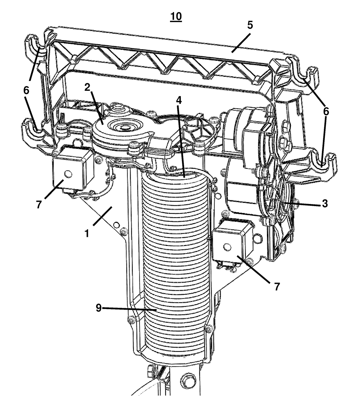
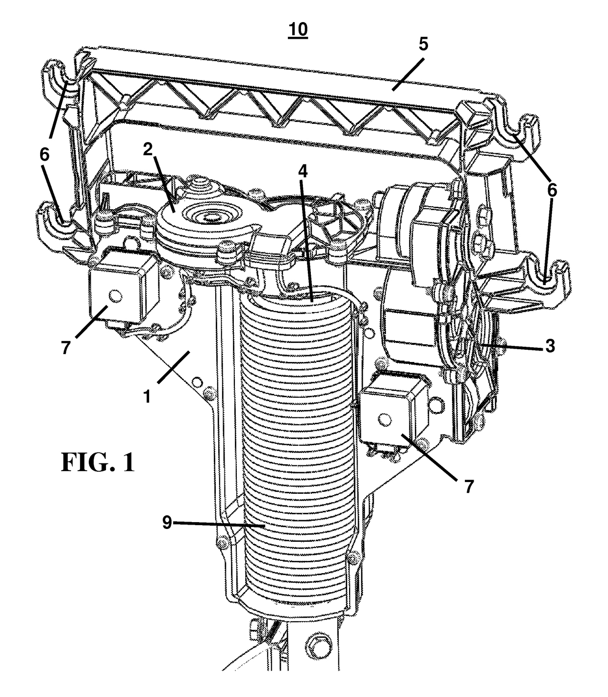
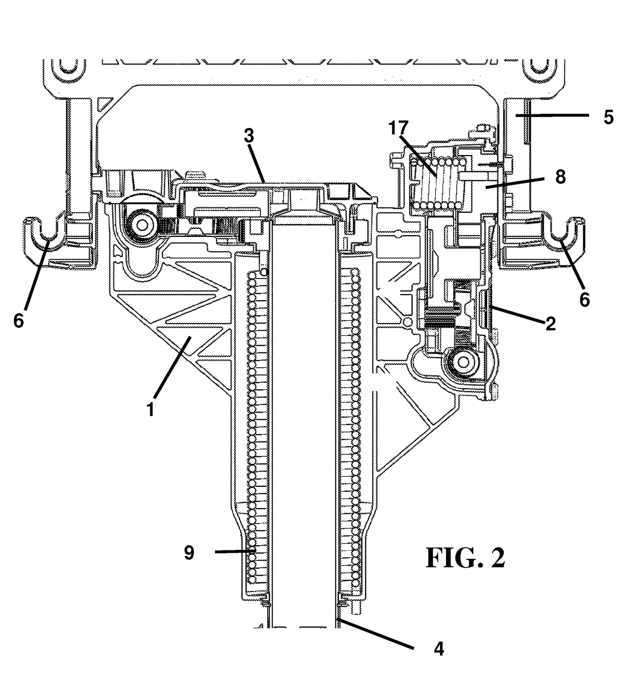
[0016]An improved heliostat assembly 10 is described herein, with reference to FIGS. 1-5. The exemplary heliostat assembly 10 is advantageously configured to provide for a biasing force during energy capture movement even when external loads are applied to the assembly, as described in greater detail herein.

[0017]An embodiment of a heliostat drive assembly 10, as illustrated in FIGS. 1 and 2, comprises a chassis 1 and two gear transmissions, wherein each gear transmission may be enclosed in a respective gear enclosure. The chassis may comprise a single element or a plurality of elements bonded together or connected via fasteners. The gear housings may be made integral with the chassis and may comprise, for example, an azimuth gear enclosure 2 and an elevation gear enclosure 3. The azimuth gear enclosure 2 may enclose an azimuth gear transmission for actuating the heliostat drive chassis about an azimuth axis. The azimuth axis may be defined as being orthogonal to the ground and pass...


PUM


Abstract

A drive assembly for a heliostat is described, wherein the drive assembly may be configured to dynamically adjust the position of an attached reflector in concentrated solar power applications. The drive assembly may be further configured to provide for biasing of the reflector to reduce backlash due to external loads. The biasing force may be provided by at least one of a spring, counterweight, or offset of the center of gravity of the reflector or other attachment, or some combination thereof.

Description

CROSS-REFERENCES TO RELATED APPLICATIONS[0001]The present application claims priority to and the benefit of U.S. Provisional Patent Application No. 61 / 881,080, filed on Sep. 23, 2013, the entire disclosure of which is incorporated herein by reference.BACKGROUND OF THE INVENTION[0002]This disclosure relates generally to heliostats having reflectors configured to redirect sun light to a target or receiver, and in particular to heliostat drive assemblies configured to dynamically control the position of the reflectors.[0003]In Concentrating Solar Power (CSP) plants, arrangements of heliostats reflect sunlight toward a receiver mounted atop a tower containing a working fluid. One type of receiver transfers incident radiant energy to the working fluid to produce high-pressure, high-temperature steam through the means of a heat exchanger or a phase change of the working fluid itself. The working fluid can be water, air, or a salt material heated to a molten state. The output steam can fac...

Claims


Application Information

Patent Timeline
Patent Type & Authority Patents(United States)
IPC IPC(8): F24J2/54F24J2/07F24J2/40F24S20/20
CPCF24J2/5427F24J2/07F24J2/405F24J2002/5437F24J2002/5462F24J2002/5493Y02E10/47F24S40/85F24S30/452F24S2030/134F24S2030/18F24S20/20F24S50/60F24S30/458F24S2030/11
Inventor PILEGAARD, ULRIK
Owner SEPCOIII ELECTRIC POWER CONSTR CO LTD
Learn More