Color mixing optics for LED illumination device

Active Publication Date: 2017-08-15
LUTRON TECH CO LLC
View PDF309 Cites 32 Cited by
  • Summary
  • Abstract
  • Description
  • Claims
  • Application Information

AI Technical Summary

Benefits of technology

[0019]Any photodetector in a multi-color illumination device with optical feedback should be placed to minimize interference from external light sources. This invention places the photodetectors within the primary optics structure (e.g., the silicone dome) for this purpose. The four photodetectors are connected in parallel to sum the photocurrent produced by each photodetector, which minimizes any spatial variation in photocurrents caused by scattering the similarly colored emission LEDs across the substrate. According to one embodiment, the photodetectors are preferably red or yellow LEDs, but could comprise silicon diodes or any other type of light detector. The red or yellow detector LEDs are preferable since silicon diodes are sensitive to infrared as well as visible light, while the LEDs are sensitive to only visible light.
[0020]LED or silicon photodetectors produce current that is proportional to incident light. Such current sources easily sum when the photodetectors are connected in parallel. When connected in parallel, the N photodetectors function as one larger detector, but with much better spatial uniformity. For instance, with only one photodetector, light from one LED in a given chain may produce much more photocurrent than light from another LED in the same chain. As the emission LEDs age and the light output decreases, the optical feedback algorithm compensates for changes in the emission LED that induces the largest photocurrent simply due to LED and d

Problems solved by technology

Philips Color Kinetics has marketed many multi-color LED products, however, most are restricted to indoor and outdoor saturated wall-washing color and color changing effects.
Color accuracy in the Hue product is susceptible to LED aging, since it does not use optical feedback to compensate for the change in luminance over time for each of the differently colored

Method used


Image

  • Color mixing optics for LED illumination device
  • Color mixing optics for LED illumination device
  • Color mixing optics for LED illumination device

Examples


Embodiment Construction

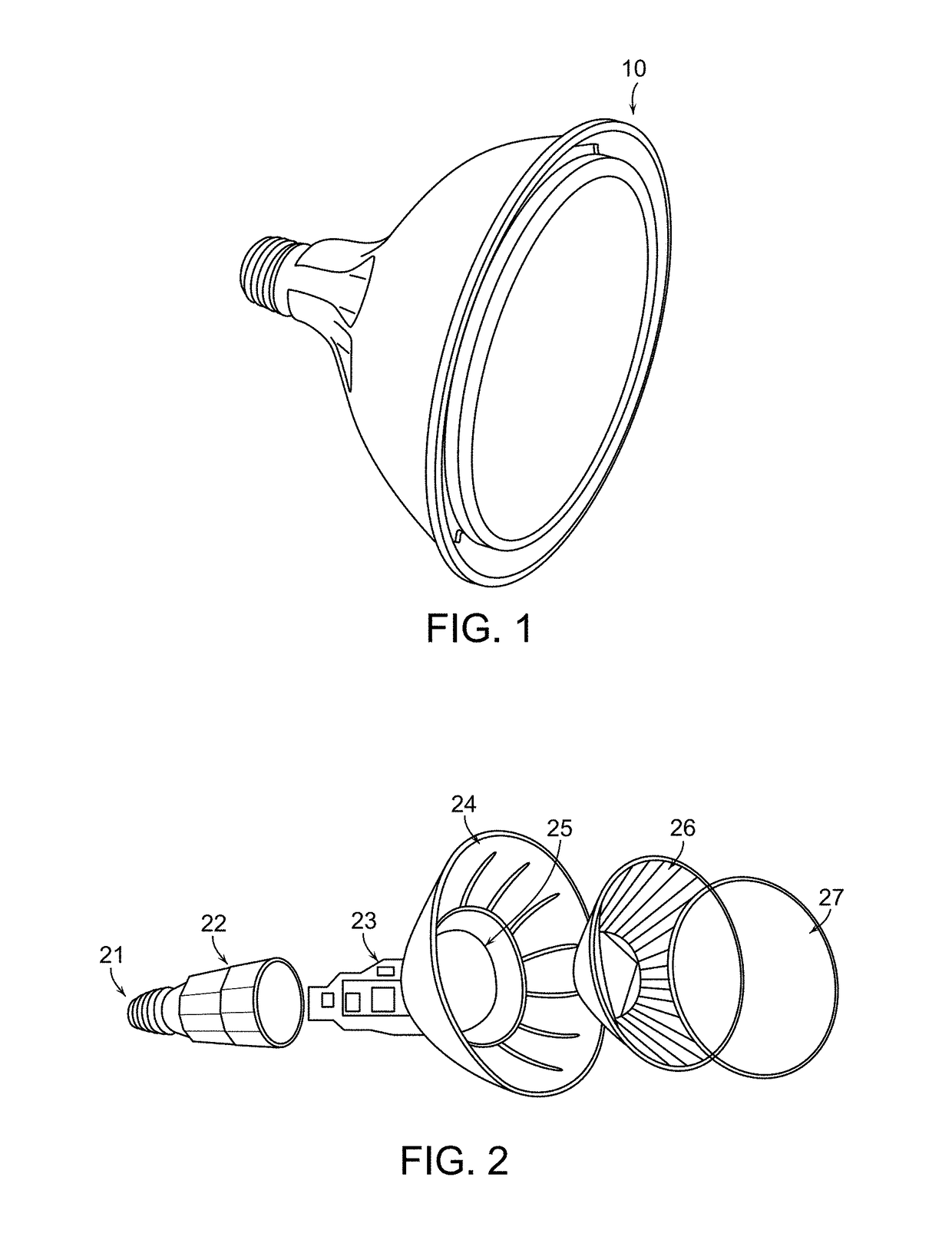
[0043]Turning now to the drawings, FIG. 1 is a picture of an example illumination device 10, which according to one embodiment, is an LED lamp with a PAR38 form factor. As described in more detail below, LED lamp 10 produces light over a wide color gamut, thoroughly mixes the color components within the beam, and uses an optical feedback system to maintain precise color over LED lifetime. LED lamp 10 is preferably powered by the AC mains and screws into any standard PAR38 fixture. The light beam produced by LED lamp 10 is substantially the same as the light beam produced by halogen PAR38 lamps with any beam angle, but typically between 10 and 40 degrees.

[0044]LED lamp 10 is just one example of a wide color gamut illumination device that is configured to provide uniform color within the beam and precise color control over LED lifetime. In addition to a PAR38 form factor, the inventive concepts described herein could be implemented in other standard downlight form factors, such as PAR...


PUM


Abstract

Illumination devices with improved color mixing optics are disclosed herein for mixing the colors produced by a multi-colored LED emitter module to produce uniform color throughout the entire beam angle of the output light beam, along with smoother edges and improved center beam intensity. Embodiments disclosed herein include a unique arrangement of multi-color LEDs within an emitter module, a unique exit lens with different patterns of lenslets on opposing sides of the lens, and other associated optical features that thoroughly mix the different color components, and as such, provide uniform color across the output beam exiting the illumination device. Additional embodiments disclosed herein include a unique arrangement of photodetectors within the primary optics structure of the LED emitter module that ensure the optical feedback system properly measures the light produced by all similarly colored emission LEDs.

Description

PRIORITY CLAIM[0001]This application claims priority to U.S. Application No. 61 / 886,471 filed Oct. 3, 2013.RELATED APPLICATIONS[0002]This application is related to the following co-pending applications: U.S. application Ser. Nos. 12 / 803,805; 12 / 806,118, which was issued as U.S. Pat. No. 8,773,336; Ser. No. 13 / 970,944, which was issued as U.S. Pat. No. 9,237,620; Ser. Nos. 13 / 970,964; 13 / 970,990; 14 / 314,530; 14 / 314,580, which was issued as U.S. Pat. No. 9,392,663; and Ser. No. 14 / 471,081—each of which is hereby incorporated by reference in its entirety.BACKGROUND[0003]1. Field of the Invention[0004]The invention relates to the addition of color mixing optics and optical feedback to produce uniform color throughout the light beam produced by a multi-color LED illumination device.[0005]2. Description of Related Art[0006]Multi-color LED illumination devices (also referred to herein as light sources, luminaires or lamps) have been commercially available for many years. For example, Cree ...

Claims


Application Information

Patent Timeline
IPC IPC(8): H05B37/02H05B33/08H05B44/00
CPCH05B33/0821H05B33/0869F21V23/0457F21Y2105/10F21K9/233F21Y2113/13H05B45/22H05B45/46F21V5/004F21V5/007
Inventor DONG, FANGXUHO, HORACE C.KNAPP, DAVID J.
Owner LUTRON TECH CO LLC
Why Eureka
Try Eureka