Eureka AIR delivers breakthrough ideas for toughest innovation challenges, trusted by R&D personnel around the world.

Turbine wheel of automotive turbocharger and method for producing the same

a technology of automotive turbocharger and turbine wheel, which is applied in the direction of engines, machines/engines, mechanical apparatus, etc., can solve the problems of deviation, high temperature strength difference, and difficulty in forging turbine wheel, and achieve stable high temperature strength and high reliability of durability li

Active Publication Date: 2017-08-22
DAIDO STEEL CO LTD
View PDF18 Cites 0 Cited by
  • Summary
  • Abstract
  • Description
  • Claims
  • Application Information

AI Technical Summary

Benefits of technology

[0027]Based on the above-described circumstances as background, the present invention has been made for the purpose of providing a turbine wheel of an automotive turbocharger including a Ni-based alloy having high reliability of durability life, in which stable high temperature strength is obtained, and a method for producing the same.
[0050]According to the present invention, a turbine wheel of an automotive turbocharger including a Ni-based alloy having high reliability of durability life in which stable high temperature strength is obtained and a method for producing the same can be provided.

Problems solved by technology

Therefore, it is difficult to produce a turbine wheel by forging, and generally, a turbine wheel is cast mainly using a Ni-based casting alloy and is used as it is (as-cast state).
On the other hand, it is viewed as problematic that regarding high temperature strength, deviation occurs among products, and to pursue its cause, observation of the state of carbide and crystal grain has been mainly made, but the solution has not been achieved.
Thus, the problems have still remained on occurrence of deviation and difference in high temperature strength.

Method used


Image

  • Turbine wheel of automotive turbocharger and method for producing the same
  • Turbine wheel of automotive turbocharger and method for producing the same
  • Turbine wheel of automotive turbocharger and method for producing the same

Examples


examples

[0111]Examples of the present invention are described below.

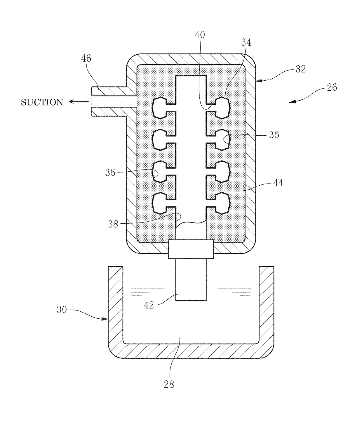
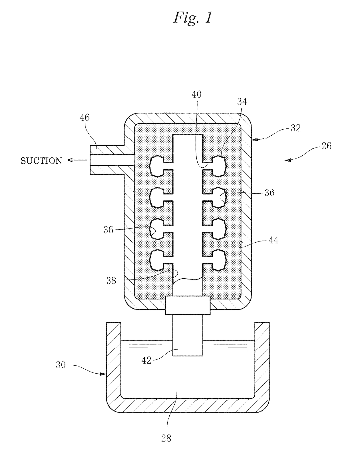
[0112]Using a Ni-based alloy having a composition of C: 0.1%, Mn: 0.03%, Si: 0.1%, Cr: 13.5%, Mo: 5.0%, Nb+Ta: 2.5%, Ti: 1.00%, Al: 6.0%, B: 0.010%, Zr: 0.08%, and Fe: 1.0%, with the remainder being Ni and unavoidable impurities, a turbine wheel 14 shown in FIG. 3B was cast by reduced pressure suction casting facilities 26 shown in FIG. 1.

[0113]In FIG. 1, 28 is a melt of a Ni-based alloy stored in a furnace 30, 32 is a reduced pressure chamber as a casting chamber, and 34 is a mold arranged therein. The mold 34 is a porous mold produced by a lost wax process.

[0114]36 is a cavity for molding a product in the mold 34, that is, a cavity for molding a turbine wheel shown in FIG. 3B, and 38 and 40 are a main passage and a branch passage, that suck the melt 28 and guide it to each cavity 36.

[0115]In the reduced pressure chamber 32, a space around the mold 34 is filled with sand (backup sand) 44.

[0116]Furthermore, the reduced pres...


PUM

PropertyMeasurementUnit
sizeaaaaaaaaaa
thicknessaaaaaaaaaa
temperatureaaaaaaaaaa

Abstract

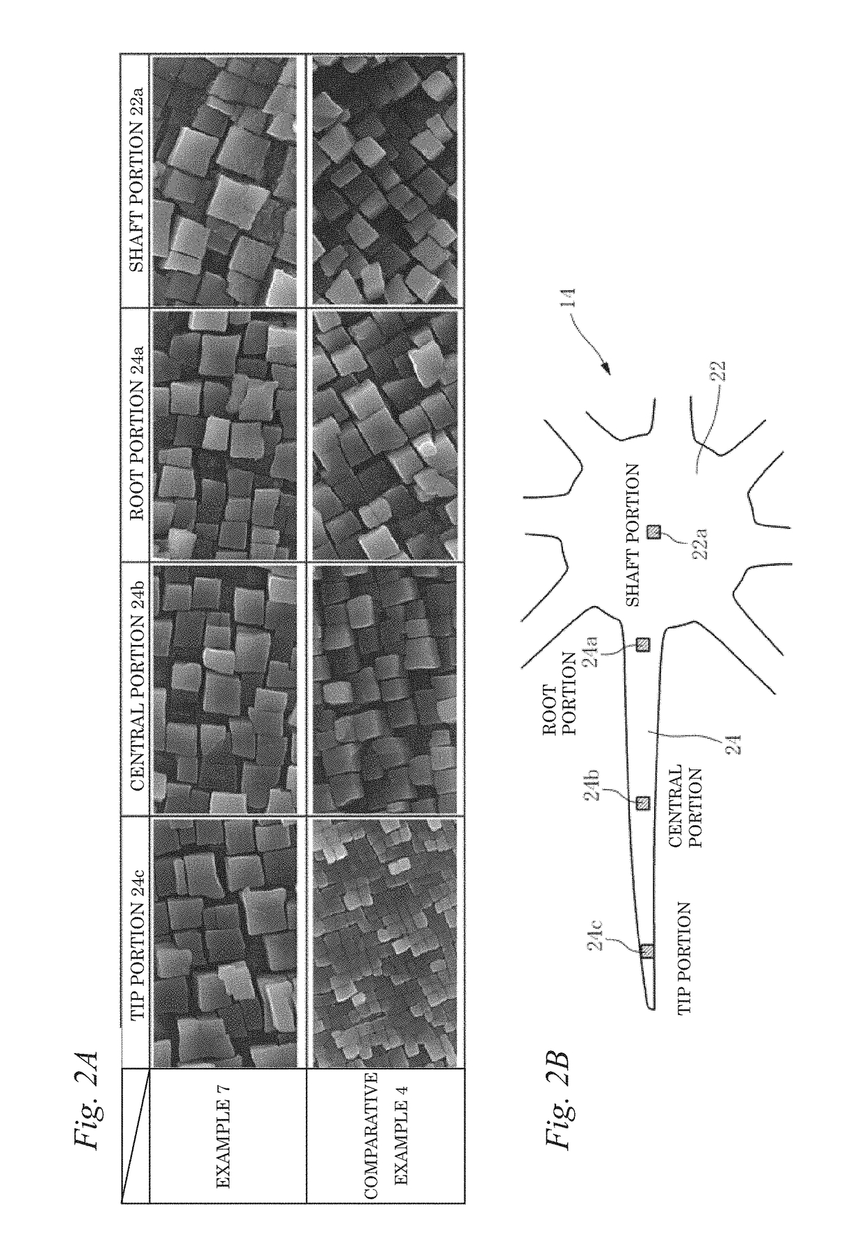
The present invention relates to a turbine wheel of an automotive turbocharger, including a Ni-based alloy having a composition which contains, in terms of mass %: C: 0.08 to 0.20%; Mn: 0.25% or less; Si: 0.01 to 0.50%; Cr: 12.0 to 14.0%; Mo: 3.80 to 5.20%; Nb+Ta: 1.80 to 2.80%; Ti: 0.50 to 1.00%; Al: 5.50 to 6.50%; B: 0.005 to 0.015%; Zr: 0.05 to 0.15%; and Fe: 0.01 to 2.5%, with the remainder being Ni and unavoidable impurities, in which the turbine wheel includes a wing part and a shaft part, and a size of γ′ phase in each site of from a tip of the wing part to the shaft part is structure-controlled so as to fall within a range of from 0.4 to 0.8 μm.

Description

FIELD OF THE INVENTION[0001]The present invention relates to a turbine wheel of an automotive turbocharger and a method for producing the same, particularly relates to a turbine wheel including a Ni-based alloy and a method for producing the same.BACKGROUND OF THE INVENTION[0002]In recent years, a turbocharger that is greatly effective to improvement of fuel efficiency is widely used in an automotive engine, particularly an automotive diesel engine, in strongly demanding improvement of fuel efficiency.[0003]Turbocharger rotates a turbine wheel utilizing an exhaust gas from an engine to drive a compressor wheel provided on the same shaft, thereby supplying high pressure air to the engine.[0004]FIG. 3A shows a structure of a general automotive turbocharger.[0005]As shown in FIG. 3A, a turbocharger 10 has a turbine wheel 14 in a turbine housing 12 and a compressor wheel 18 in a compressor housing 16, and the turbine wheel 14 and the compressor wheel 18 are integrally connected in a rot...

Claims


Application Information

Patent Timeline
Patent Type & Authority Patents(United States)
IPC IPC(8): B22D18/06C22C19/05F01D5/28
CPCC22C19/056B22D18/06F01D5/28
Inventor SUMI, YOSHINORITAKABAYASHI, HIROYUKI
Owner DAIDO STEEL CO LTD
Why Eureka
Eureka Blog
Learn More