
Enhanced methods for operating refueling station tube-trailers to reduce refueling cost

a technology of refueling station and enhanced methods, which is applied in the direction of vessel construction details, container filling under pressure, transportation and packaging, etc., can solve the problems of limited use of hydrogen fuel cell electric vehicles (hfcevs), and achieve the effect of reducing hydrogen refueling cos

Active Publication Date: 2017-08-22
UCHICAGO ARGONNE LLC
View PDF8 Cites 11 Cited by
  • Summary
  • Abstract
  • Description
  • Claims
  • Application Information

AI Technical Summary

Benefits of technology

The present invention provides a method and apparatus for operating a hydrogen refueling station that reduces the cost of refueling. The refueling station includes source tube-trailers and a compressor. A control unit is used to manage the refueling process. The refueling station can operate in different modes depending on its initial state, and the system is assessed at the end of each mode to identify its status and select the next mode of operation. The technical effect of this invention is to provide a more efficient and cost-effective way to refuel hydrogen-based vehicles.

Problems solved by technology

The use of hydrogen fuel cell electric vehicles (HFCEVs) is limited by available hydrogen refueling stations.

Method used


Image

  • Enhanced methods for operating refueling station tube-trailers to reduce refueling cost
  • Enhanced methods for operating refueling station tube-trailers to reduce refueling cost
  • Enhanced methods for operating refueling station tube-trailers to reduce refueling cost

Examples


Embodiment Construction

[0016]In the following detailed description of embodiments of the invention, reference is made to the accompanying drawings, which illustrate example embodiments by which the invention may be practiced. It is to be understood that other embodiments may be utilized and structural changes may be made without departing from the scope of the invention.

[0017]The terminology used herein is for the purpose of describing particular embodiments only and is not intended to be limiting of the scope of the invention. As used herein, the singular forms “a”, “an” and “the” are intended to include the plural forms as well, unless the context clearly indicates otherwise. It will be further understood that the terms “comprises” and / or “comprising,” when used in this specification, specify the presence of stated features, integers, steps, operations, elements, and / or components, but do not preclude the presence or addition of one or more other features, integers, steps, operations, elements, componen...


PUM


Abstract

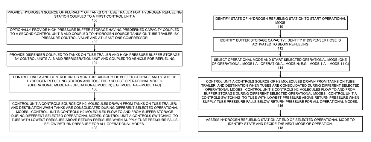
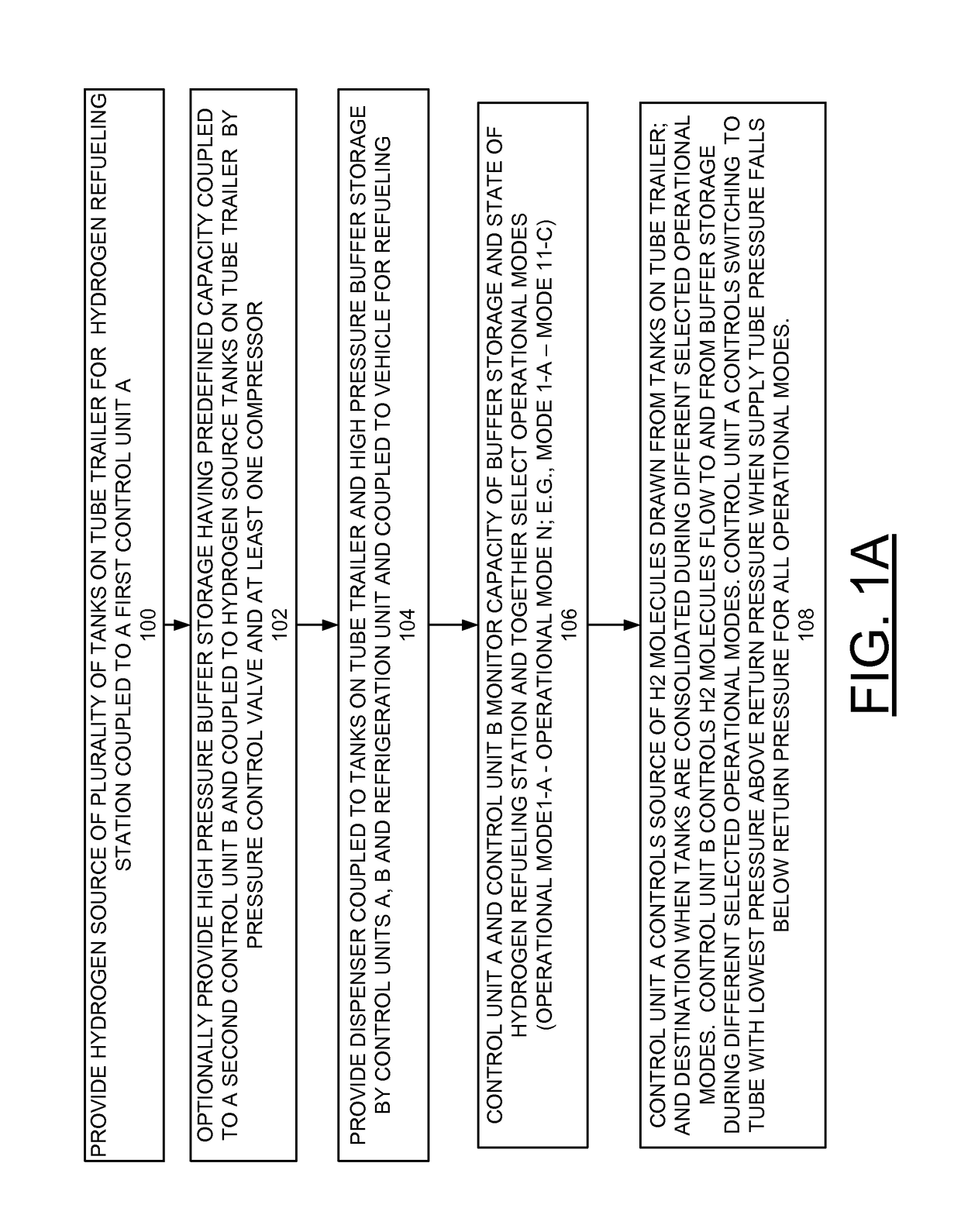
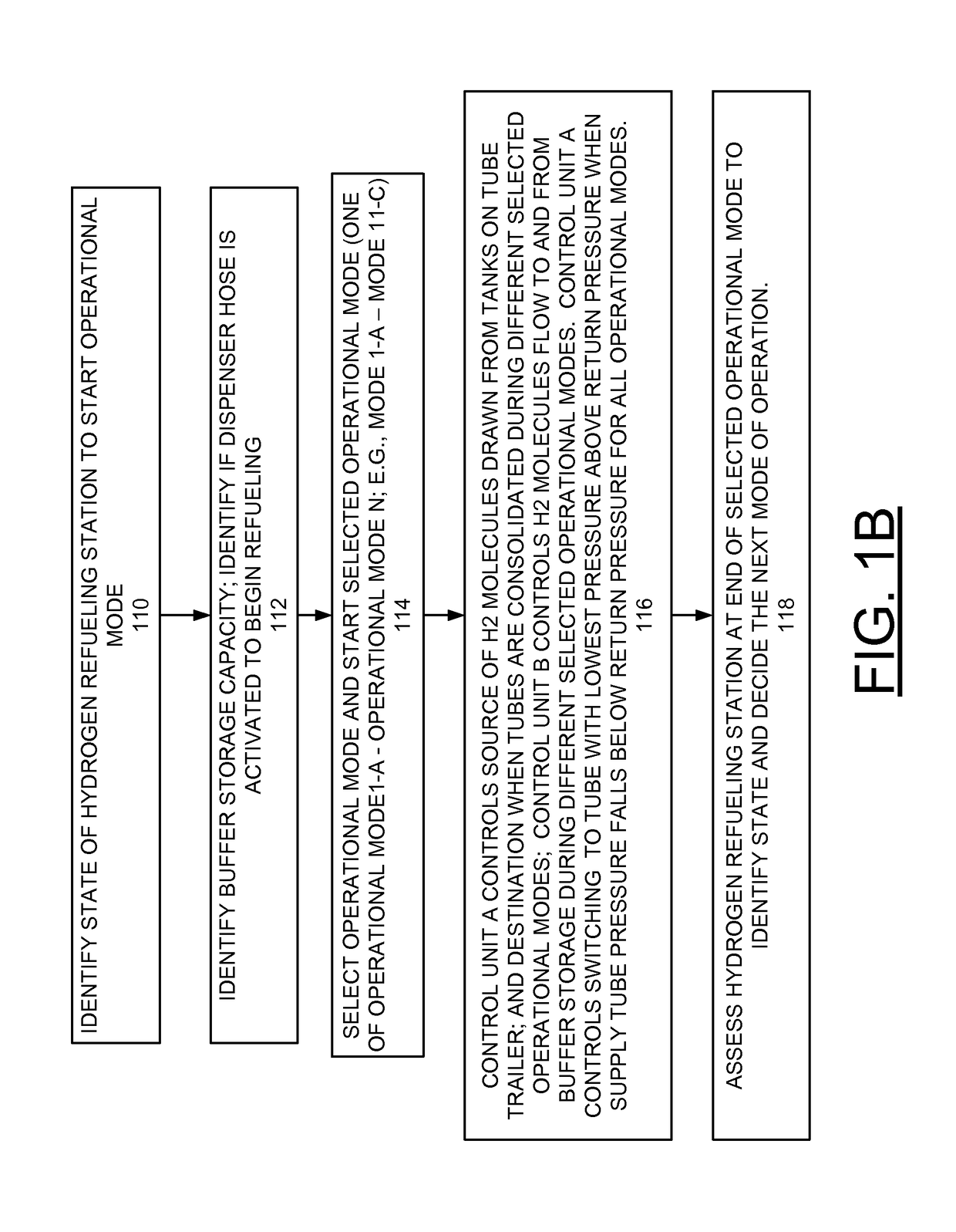
A method and apparatus are provided for operating a refueling station including source tube-trailers and at least one compressor to reduce refueling cost. The refueling station includes a gaseous fuel supply source including a plurality of tanks on a tube trailer coupled to a first control unit, and high pressure buffer storage having predefined capacity coupled to a second control unit and the first tanks by a pressure control valve and the first control unit, and at least one compressor. The refueling station is operated at different modes depending on a state of the refueling station at the beginning of each operational mode. The refueling system is assessed at the end of each operational mode to identify the state of the system and select a next mode of operation. The operational modes include consolidating hydrogen, or any gaseous fuel, within the tubes mounted on the trailer.

Description

CONTRACTUAL ORIGIN OF THE INVENTION[0001]The United States Government has rights in this invention pursuant to Contract No. DE-AC02-06CH11357 between the United States Government and UChicago Argonne, LLC representing Argonne National Laboratory.FIELD OF THE INVENTION[0002]The present invention relates to a method and apparatus for operating a hydrogen refueling station including source tube-trailers and at least one compressor to reduce refueling cost for hydrogen, and gaseous fuels.DESCRIPTION OF THE RELATED ART[0003]While hydrogen refueling stations and hydrogen refueling is described in detail in the following description, it should be understood that the present invention is not limited to hydrogen. For example, the present invention advantageously is used with various gaseous fuels including compressed natural gas (CNG).[0004]The use of hydrogen fuel cell electric vehicles (HFCEVs) is limited by available hydrogen refueling stations. An adequate hydrogen refueling network is n...

Claims


Application Information

Patent Timeline
Patent Type & Authority Patents(United States)
IPC IPC(8): B65B37/00F17C5/00F17C5/06F17C5/04
CPCF17C5/06F17C5/007F17C5/04F17C2205/0107F17C2205/0134F17C2205/0326F17C2221/012F17C2223/0123F17C2223/035F17C2225/0123F17C2225/036F17C2227/0157F17C2227/0185F17C2227/0337F17C2227/043F17C2250/01F17C2250/03F17C2260/046F17C2265/065F17C2270/0139F17C2270/0171Y02E60/321Y02E60/32
Inventor ELGOWAINY, AMGADREDDI, KRISHNA
Owner UCHICAGO ARGONNE LLC
Learn More