Low cost 3D radar imaging and 3D association method from low count linear arrays for all weather autonomous vehicle navigation

a low-cost, autonomous vehicle technology, applied in the direction of reradiation, measurement devices, instruments, etc., can solve the problems of autonomous vehicle systems that are unable to navigate safely, affecting localization, and compromising optical sensors

Active Publication Date: 2017-08-22
RFNAV INC
View PDF8 Cites 85 Cited by
  • Summary
  • Abstract
  • Description
  • Claims
  • Application Information

AI Technical Summary

Benefits of technology

[0011]In one aspect, the invention provides a high definition RF radar system for an autonomous vehicle. The high definition RF radar system includes a first array and a second array. The first array can include a first plurality of receive antenna elements provided by a first receive switch network and a first plurality of transmit antenna elements provided by a first transmit switch network. The second array can include a second plurality of receive antenna elements provided by a second receive switch network and a second plurality of transmit antenna elements provided by a second transmit switch network. The high definition RF radar system also includes a Boolean associator configured to receive data from the first array and the second array. The Boolean associator can determine that the received data represents a true target detection and target position of an object when a plurality of constraints is met. The plurality of constraints includes at least one first type of constraint and at least one second type of constraint. The high definition RF radar system also can include a scene imaging unit. The scene imaging unit is configured to receive a plurality of true target detections and target positions from the Boolean associator and provide at least one of object detection information and scene imaging information to one or more systems of the autonomous vehicle. The first array can be disposed on the autonomous vehicle with a first orientation such that the first plurality of receive antenna elements and the first plurality of transmit antenna elements are configured for detection in a first direction. The second array can be disposed on the autonomous vehicle with a second orientation such that the second plurality of receive antenna elements and the second plurality of transmit antenna elements are configured for detection in a second direction. The first array is oriented generally orthogonal to the second array.

Problems solved by technology

Optical sensors are compromised and can become useless in foul weather and other adverse conditions.
The loss of optical sensor data results in autonomous vehicle systems that are unable to navigate safely in the presence of foul weather and other adverse conditions.
Further, even when the air path is visually clear, localization can be compromised when only surface visual obscurants are present, including: wet or flooded road surfaces, road and ground covers that include accumulated snow, sand, dust, leaf, pollen, and / or other surface obscurants.
Another problem with the state-of-the-art autonomous vehicle localization occurs under GPS compromised conditions combined with foul weather and / or other adverse conditions.
Urban canyons, with their long GPS shadows and multipath opportunities, result in mean and variance position errors frequently exceeding 10 feet or more.
Unfortunately the latter approach for recovery of self-position in the presence of GPS multipath and outages is viable only under benign weather conditions.
The presence of visual air-borne and / or surface obscurants increases the position errors derived from passive and active optical sensors such as cameras and Lidar.

Method used


Image

  • Low cost 3D radar imaging and 3D association method from low count linear arrays for all weather autonomous vehicle navigation
  • Low cost 3D radar imaging and 3D association method from low count linear arrays for all weather autonomous vehicle navigation
  • Low cost 3D radar imaging and 3D association method from low count linear arrays for all weather autonomous vehicle navigation

Examples


Embodiment Construction

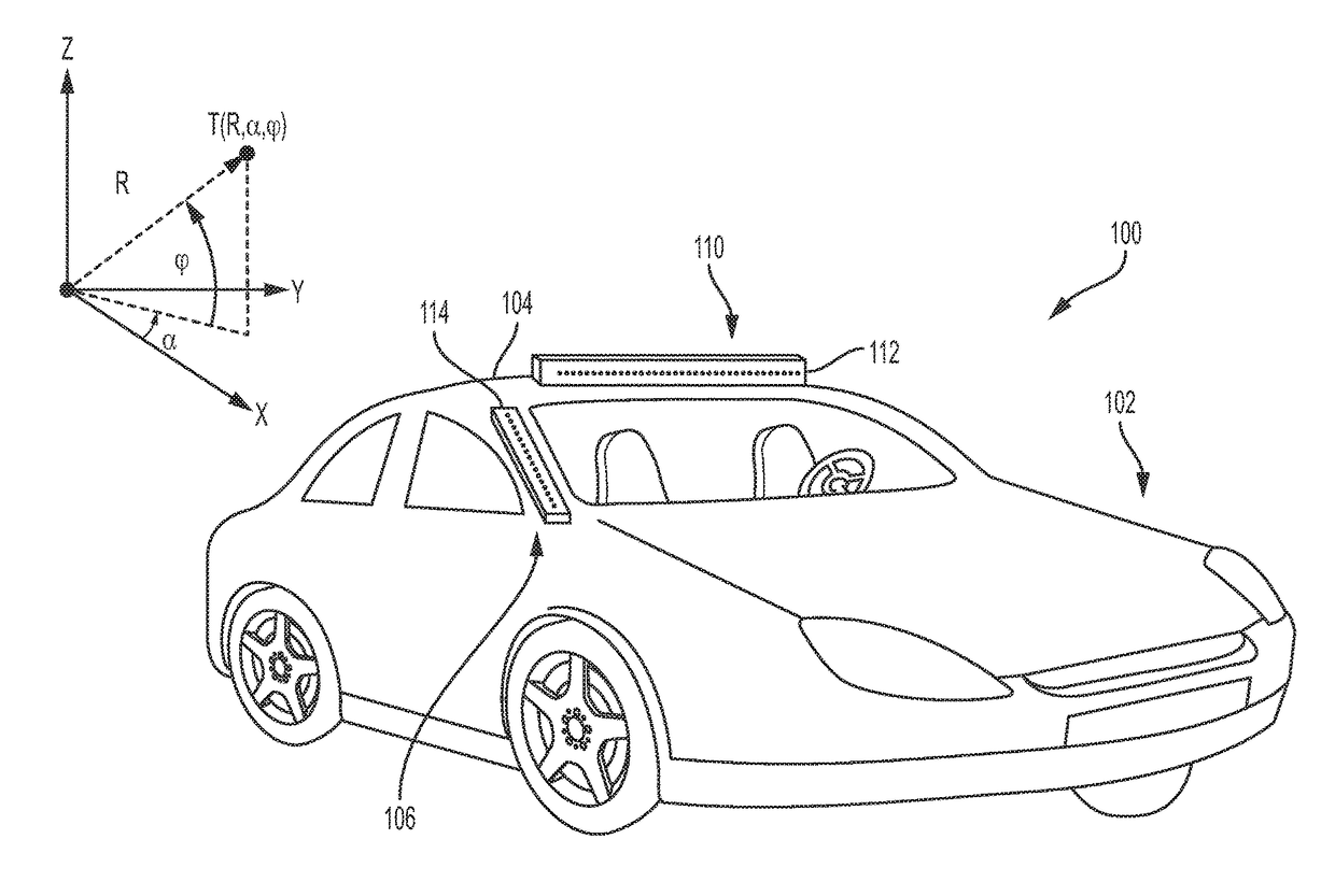
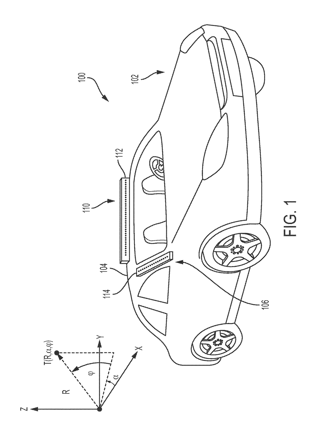
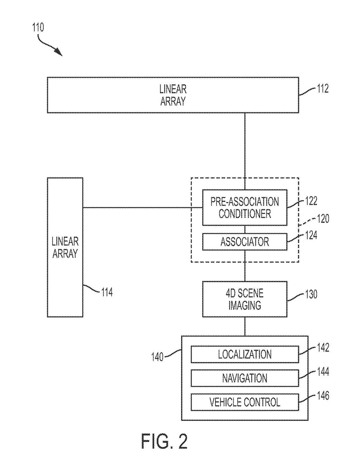
[0044]A high-definition radio-frequency (RF) domain imaging sensor for use by autonomous vehicles is disclosed in the exemplary embodiments. In an exemplary embodiment, the high-definition RF domain imaging sensor can be a 4D (3D and Doppler velocity) high definition RF radar system that detects objects to image and / or interpret a scene in both visually clear and opaque weather, as well as when road surface and other features are obscured by precipitation or other adverse conditions. Real time filtered data obtained from the RF radar system also provides sufficient resolution for both localization and navigation of an autonomous vehicle in dense urban environments when GPS is unavailable or compromised. In some embodiments, the high-definition RF radar system's outputs can be further integrated with other traditional autonomous vehicle sensors, including, but not limited to: GPS / INS, cameras, Lidar, ultrasound, wheel encoders, and / or other known conventional vehicle sensors, to perm...


PUM


Abstract

A low cost, all weather, high definition RF radar system for an autonomous vehicle is described. The high definition RF radar system generates true target object data suitable for imaging, scene understanding, and all weather navigation of the autonomous vehicle. The high definition RF radar system includes a pair of independent orthogonal linear arrays. Data from both linear arrays is fed to a processor that performs data association to form true target detections and target positions. A Boolean association method for determining true target detections and target positions reduces many of the ghosts or incorrect detections that can produce image artifacts. The high definition RF radar system provides near optimal imaging in any dense scene for autonomous vehicle navigation, including during visually obscured weather conditions such as fog.

Description

CROSS-REFERENCE TO RELATED APPLICATIONS[0001]This non-provisional patent application claims the benefit of priority under 35 U.S.C. §119(e) to U.S. Provisional Patent Application Ser. No. 62 / 312,681, which was filed in the U.S. Patent and Trademark Office on Mar. 24, 2016 and entitled “Ultra Low Cost Imaging Radar Aperture for All Weather Navigation with Self-Driving Cars”, this non-provisional patent application also claims the benefit of priority under 35 U.S.C. §119(e) to U.S. Provisional Patent Application Ser. No. 62 / 314,372, which was filed in the U.S. Patent and Trademark Office on Mar. 28, 2016 and entitled “Low Cost 3D Radar Imaging and 3D Association Method from Low Count Linear Arrays for All Weather Navigation with Self-Driving Cars”, this non-provisional patent application also claims the benefit of priority under 35 U.S.C. §119(e) to U.S. Provisional Patent Application Ser. No. 62 / 341,939, which was filed in the U.S. Patent and Trademark Office on May 26, 2016 and enti...

Claims


Application Information

Patent Timeline
Patent Type & Authority Patents(United States)
IPC IPC(8): G01S13/93G01S13/89G01S13/86G01S13/931
CPCG01S13/89G01S13/931G01S13/86G01S13/865G01S13/867G01S2013/9342G01S2013/935G01S2013/9346G01S2013/93276G01S2013/93273G01S2013/9318G01S2013/9319G01S2013/93185
Inventor PAVEK, RICHARD E.WILLEY, JEFFERSON M.
Owner RFNAV INC
Why Eureka
Try Eureka