
Method for treating combustible material and installation

a technology of combustible materials and installations, applied in the field of combustible material treatment, can solve problems such as damage to waste heat boilers or the like, and achieve the effects of reducing the amount of combustible materials remaining unmelted, reducing the loss of valuable metals, and increasing the treatment capacity of combustible materials

Active Publication Date: 2017-08-29
MITSUBISHI MATERIALS CORP
View PDF34 Cites 0 Cited by
  • Summary
  • Abstract
  • Description
  • Claims
  • Application Information

AI Technical Summary

Benefits of technology

[0012]Further, since the molten substance and the combustible material are not sufficiently stirred, the combustible material remains unmelted in the molten substance and is discharged with slag outside the system while containing the valuable metal components to cause slag loss of valuable metals. Particularly, in the related art, since the combustible material is press-formed into a lump, the combustible material easily remains unmelted.
[0041]According to the present invention, the combustible material can be brought into sufficient contact with the molten substance and the combustion heat of the combustible material can be effectively used for heating the molten substance. The combustible material remaining unmelted is reduced and the slag loss of the valuable metals is suppressed so that the treatment capacity of the combustible material can be increased. The running cost can be reduced and the inner wall of the gas zone of the furnace body and the waste heat boiler can be prevented from being damaged.

Problems solved by technology

Thus, there is a concern of damaging the waste heat boiler or the like.

Method used


Image

  • Method for treating combustible material and installation
  • Method for treating combustible material and installation
  • Method for treating combustible material and installation

Examples


examples

[0114]Hereinafter, examples of the present invention will be described in detail. However, the present invention is not limited to the examples.

example

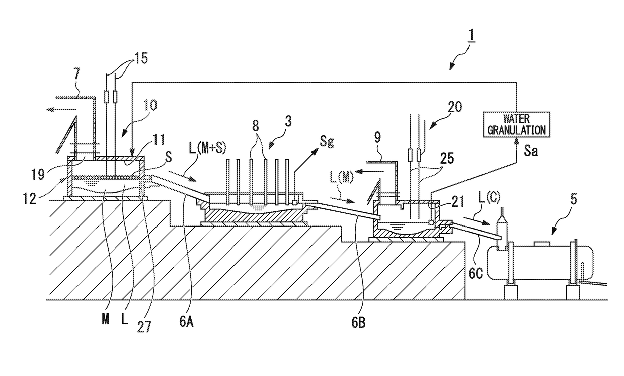
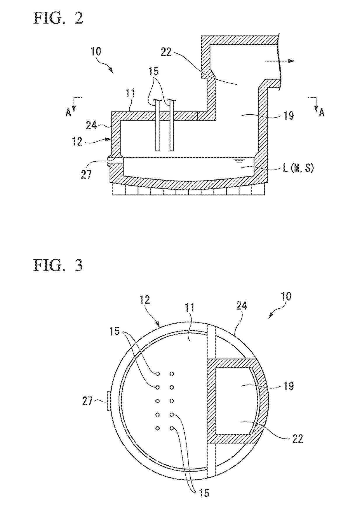
[0115]First, as Example of the present invention, an operation of pulverizing combustible scrap (combustible material, referred to as simply scrap below) containing valuable metals and blowing the pulverized scarp onto a molten substance surface of molten substance L in an S furnace (smelting furnace 10) of a Mitsubishi continuous copper-smelting process from lance pipes 15 with oxygen-enriched air was performed.

[0116]The scrap is mainly composed of substrate scrap and includes a combustible resin material which is the main component, Cu, SiO2, CaO, Al2O3, and a trace amount of Au and Ag. In addition, the scrap was crushed by a crusher so as to have a particle size of 10 mm or less.

[0117]The crushed scrap and copper ores were mixed and dried using a rotary drier, and then charged into the furnace from ten lance pipes 15 provided on the ceiling wall 11 of the S furnace. Regarding the amount of the charged copper ores and scrap, the amount of the copper ores was 101 tons (hereinafter,...


PUM

PropertyMeasurementUnit
specific gravityaaaaaaaaaa
outer diameteraaaaaaaaaa
particle sizeaaaaaaaaaa

Abstract

A method for treating combustible material of the present invention includes providing a pipe opened to a molten substance surface above the molten substance surface of molten substance stored in a furnace body for smelting nonferrous metals, and blowing combustible material containing valuable metals and oxygen-enriched air into the molten substance surface of the molten substance from the pipe.

Description

TECHNICAL FIELD[0001]The present invention relates to a method for treating combustible material by charging and melting combustible material (combustible scrap) containing valuable metals (such as Cu, Au, Ag, Pt, and Pd), such as waste electronic components or waste electronic substrates, into molten substance stored in a furnace body in a smelting furnace such as a continuous copper-smelting installation, a smelting furnace, and a continuous copper-smelting installation used for the implementation thereof.[0002]Priority is claimed on Japanese Patent Application No. 2013-130944, filed Jun. 21, 2013, the content of which is incorporated herein by reference.BACKGROUND ART[0003]In waste such as waste electronic components or waste electronic substrates (combustible scrap, referred to as combustible materials below), valuable metals such as copper (Cu), gold (Au), silver (Ag), platinum (Pt), and palladium (Pd) are contained together with combustible plastics.[0004]While such combustibl...

Claims


Application Information

Patent Timeline
Patent Type & Authority Patents(United States)
IPC IPC(8): C22B15/00F27D3/16F27B19/04B09B3/00C22B7/00C22B15/04F27D3/18C22B5/02
CPCC22B15/0052F27B19/04C22B15/0056B09B3/0083C22B5/02C22B7/001C22B15/00C22B15/005C22B15/0036F27D3/16F27D3/18F27D2003/168F27D2003/185B09B3/40Y02P10/20
Inventor OGUMA, NOBUHIROISHIKAWA, SHIGERUTAKAGI, MAKOTOMIZUTA, YUJI
Owner MITSUBISHI MATERIALS CORP
Learn More