Methods and apparatuses for processing or defining luminance/color regimes

a luminance/color regime and luminance technology, applied in the field of methods and apparatuses for processing or defining luminance/color regimes, can solve the problems of affecting the quality the change of the actual display in the viewer's living room, and the lcd of the actual display, so as to achieve good quality and high dynamic range

Active Publication Date: 2017-09-05
KONINKLJIJKE PHILIPS NV
View PDF20 Cites 5 Cited by
  • Summary
  • Abstract
  • Description
  • Claims
  • Application Information

AI Technical Summary

Benefits of technology

[0024]Lastly, and for good reasons (e.g., retraining of highly specialized camera operators), technical standards are resistant to change. The disappearing PAL standard is not going to be updated anymore. However, new standards will emerge taking into account the changed image reproduction environment, and taking into account the standard's usefulness with a view towards the future such as ever increasing camera and display quality. For example, increased camera quality can include + / −14 bit. In addition, even plain consumers are using ever increasing quality cameras, which may, with their automatic optimization algorithms in the future, yield-apart from artistic input—better results than what the average old days camera operator was producing. Furthermore, the plain consumers may want to see their pictures of monument valley on their HDR display as if they were still there.
[0025]Accordingly, the embodiments of the present disclosure offer solutions to further improve the controllability of what an artist would like people to see, versus what would be displayed, e.g., on a home television. In other words, what an artist / creator on the creation side would like people to see, versus what would be displayed on a rendering / receiving side display having a given display quality can take several forms. The several forms can depend on the kind of artist and the artist's preferences, from (i) an “I mostly want to do nothing, letting the viewer or television manufacturer doing the controlling—view” in which, e.g., only severe modifications of the content as finally rendered by the display are forbidden, on the one side of the spectrum of control options, to (ii) on the other side of the spectrum, attempts to bring a rendering as close as possible to an ideal reproduction of what the artist intended, given the rendering side display limitations, e.g., a display white luminance of the rending side display.

Problems solved by technology

Whereas evolution in movie theatres was somewhat slower, a problem started occurring already that actual displays in the viewer's living room had become LCDs and changed in their display properties such as color primaries, tone reproduction, etc.
However, with the appearance of high dynamic range (HDR) displays, such a prior solution became unfeasible: one just cannot pretend that a first display which is physically (as to black level, grey level controllability, brightness of peak white, etc.) very different from another second display “can be made to behave exactly like” that second (ideal) display.
This prior solution might work if one really wanted to emulate exactly on a current high quality high dynamic range display the behavior of a low quality display of the 1950s, but that is not how people want to use their new high quality displays (why buy a high quality display if it only shows low quality output).
However, this may have several visual disadvantages regarding the actual look of the finally rendered pictures, e.g., incorrect darkness or black regions, cartoonization of the content by excessively increasing the saturation, staircase patterns in gradients such as the sky, due to the fact that the few available codes in the image / video signal are stretched excessively, etc.

Method used


Image

  • Methods and apparatuses for processing or defining luminance/color regimes
  • Methods and apparatuses for processing or defining luminance/color regimes
  • Methods and apparatuses for processing or defining luminance/color regimes

Examples


Embodiment Construction

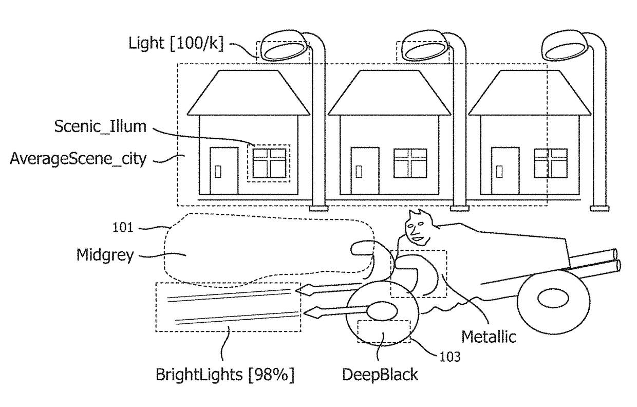
[0053]With reference first to FIG. 8, there is shown a couple of illustrative examples of the many possible HDR scenes a HDR system of the future (e.g., connected to a 1000 nit PB rendering display) may need to be able to correctly handle, i.e., by rendering the appropriate luminances for all objects / pixels in the image. E.g., ImSCN1 is a sunny outdoors image from a western movie, whereas ImSCN2 is a nighttime image. What makes HDR image rendering different from how it always was in the LDR era which ended only a couple of years ago, is that the LDR had such a limited dynamic range (about PB=100 nit, and black level +−0.1 to 1 nit), that mostly only the reflectivities of the objects could be shown (which would fall between 90% for good white and 1% for good black). So one had to show the objects independent of their illumination, and couldn't at the same time faithfully show all the sometimes highly contrasty illuminations of the scene that could happen. In practice that meant that ...


PUM

PropertyMeasurementUnit
peak brightnessaaaaaaaaaa
luminanceaaaaaaaaaa
luminanceaaaaaaaaaa

Abstract

To allow a better coordination between an image creation artist such as a movie director of photography and the final viewer, via a receiving-side display and its corresponding image processing, a method of adding display rendering specification information to an input image signal (I) comprises determining descriptive data (D) that includes at least identification information for at least one luminance regime subset of pixels of an input image; and encoding the descriptive data (D) into an output description data signal (DDO), relatable to an output image signal (O) based upon an input image signal (I), of the descriptive data (D) in a technical format standardized to be intended for use by a receiving-side display to control its image processing for changing the color properties of its rendered images.

Description

CROSS REFERENCE TO RELATED APPLICATION[0001]This application is a continuation-in-part application of co-pending U.S. patent application Ser. No. 13 / 577,930, filed on Aug. 9, 2012, which is the National Stage Application of PCT / IB2011 / 050767, filed Feb. 24, 2011, which claims the priority of EP Application No. 10155277.6, filed Mar. 3, 2010, the entire contents of which are incorporated herein by reference.FIELD OF THE INVENTION[0002]The invention relates to a method of adding image defining information to an input image signal, an image analysis apparatus for adding image defining information to image pixel information of an input image signal, and similarly corresponding to what this method and apparatus do at the image production side, a method of processing an input image signal to be rendered based on image defining information related to the input image signal, an apparatus for processing an input image signal to be rendered based on image defining information related to the i...

Claims


Application Information

Patent Timeline
Patent Type & Authority Patents(United States)
IPC IPC(8): G11B27/11H04N9/68H04N5/77H04N11/24H04N19/46H04N5/20G11B27/031H04N9/82
CPCG11B27/11G11B27/031H04N5/20H04N5/77H04N9/68H04N9/8205H04N11/002H04N19/46G09G2320/0271G09G2320/0276H04N11/24
Inventor MERTENS, MARK JOZEF WILLEM
Owner KONINKLJIJKE PHILIPS NV
Why Eureka
Try Eureka