
Coil arrangement for MPI

a coil arrangement and coil technology, applied in the field of coil arrangement, can solve the problems that the design of the coil arrangement and the methods described so far are not optimal for human beings

Active Publication Date: 2017-09-12
KONINKLJIJKE PHILIPS NV
View PDF32 Cites 3 Cited by
  • Summary
  • Abstract
  • Description
  • Claims
  • Application Information

AI Technical Summary

Benefits of technology

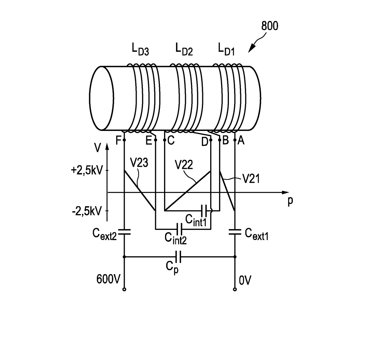
The patent text describes a method to reduce the voltage towards ground and prevent excessive potential differences between neighboring windings in a magnetic resonance imaging (MRI) apparatus. This is achieved by splitting the drive field coil into multiple coil segments and inverting the winding direction between them. Additionally, the text suggests using a shielding material to prevent magnetic interference with the measurement signal caused by the drive field coil. The technical effect is improved performance and accuracy of the MRI apparatus.

Problems solved by technology

Further, the design of the MPI apparatus and methods described so far are not yet optimal for human beings.

Method used


Image

  • Coil arrangement for MPI
  • Coil arrangement for MPI
  • Coil arrangement for MPI

Examples


Embodiment Construction

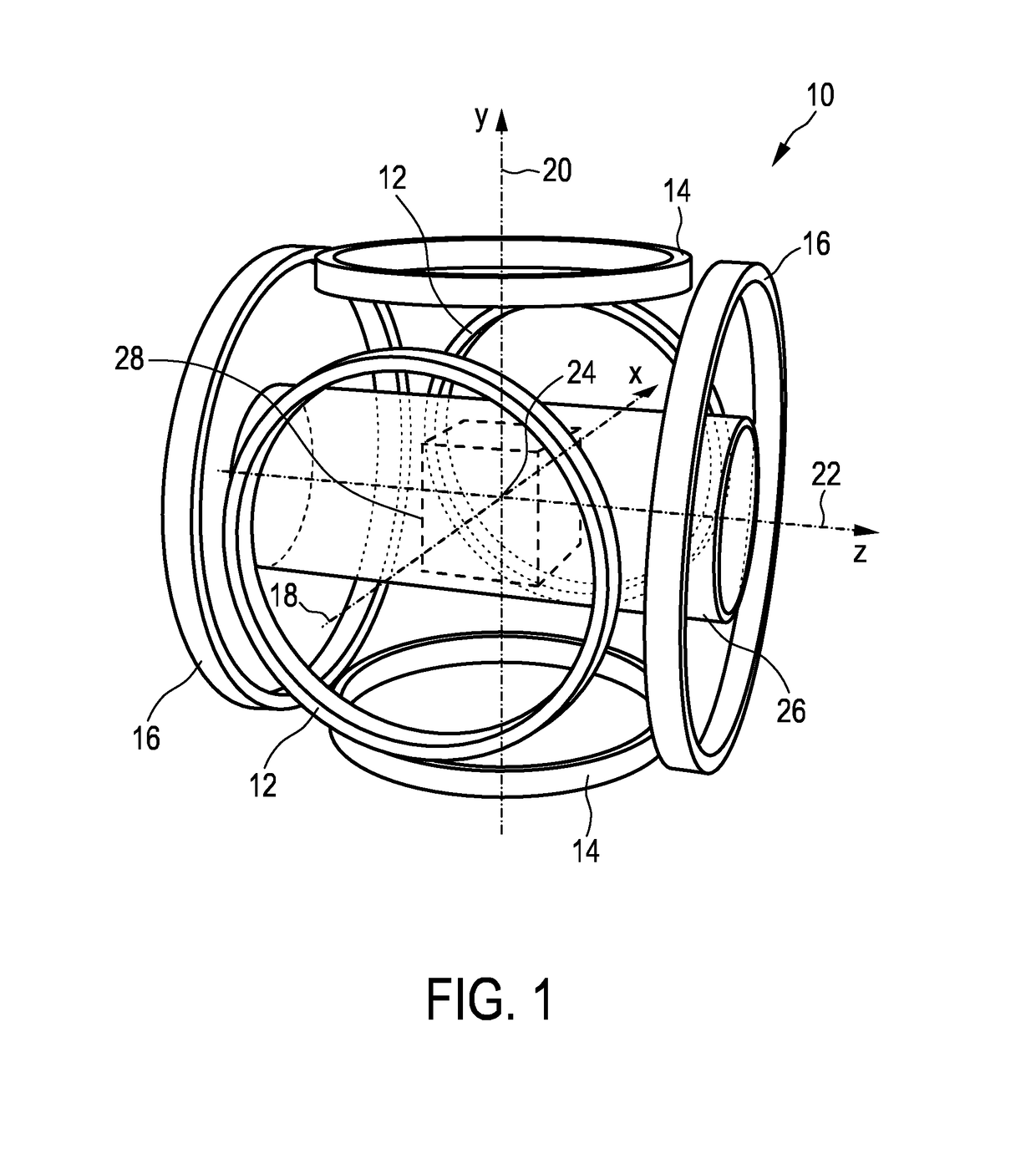
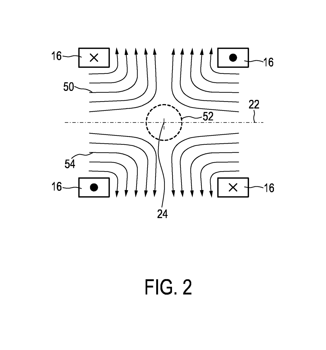
[0083]Before the details of the present invention shall be explained, basics of magnetic particle imaging shall be explained in detail with reference to FIGS. 1 to 4. In particular, four embodiments of an MPI scanner for medical diagnostics will be described. An informal description of the data acquisition will also be given. The similarities and differences between the different embodiments will be pointed out. Generally, the present invention can be used in all these different embodiments of an MPI apparatus.

[0084]The first embodiment 10 of an MPI scanner shown in FIG. 1 has three pairs 12, 14, 16 of coaxial parallel circular coils, these coil pairs being arranged as illustrated in FIG. 1. These coil pairs 12, 14, 16 serve to generate the selection field as well as the drive and focus fields. The axes 18, 20, 22 of the three coil pairs 12, 14, 16 are mutually orthogonal and meet in a single point, designated the isocenter 24 of the MPI scanner 10. In addition, these axes 18, 20, 2...


PUM

PropertyMeasurementUnit
diameteraaaaaaaaaa
angleaaaaaaaaaa
frequencyaaaaaaaaaa

Abstract

The present invention relates to a coil arrangement, in particular for use in a magnetic particle imaging apparatus (100), comprising a coil split into at least two coil segments, wherein the winding direction is inverted between at least one coil segment to another coil segment, and a capacitor coupled between at least two adjacent coil segments. Further, the present invention relates to such a magnetic particle imaging apparatus, in particular an apparatus (100) for influencing and / or detecting magnetic particles in a field of view (28), which apparatus comprises selection means and drive means (120) wherein at least one drive field coil and / or at least one selection field coil representing a selection field element is implemented by a coil arrangement as proposed according to the present invention.

Description

CROSS-REFERENCE TO PRIOR APPLICATIONS[0001]This application is the U.S. National Phase application under 35 U.S.C. §371 of International Application Serial No. PCT / IB2012 / 056803, filed on Nov. 28, 2012, which claims the benefit of U.S. Application Ser. No. 61 / 566,034, filed on Dec. 2, 2011. These applications are hereby incorporated by reference herein.FIELD OF THE INVENTION[0002]The present invention relates to a coil arrangement, in particular for use in a magnetic particle imaging apparatus. Further, the present invention relates to such a magnetic particle imaging apparatus, in particular an apparatus for influencing and / or detecting magnetic particles in a field of view.BACKGROUND OF THE INVENTION[0003]Magnetic Particle Imaging (MPI) is an emerging medical imaging modality. The first versions of MPI were two-dimensional in that they produced two-dimensional images. Newer versions are three-dimensional (3D). A four-dimensional image of a non-static object can be created by combi...

Claims


Application Information

Patent Timeline
Patent Type & Authority Patents(United States)
IPC IPC(8): G01V3/00H01F7/20A61B5/05G01R33/385
CPCG01R33/385A61B5/0515H01F7/20
Inventor SCHMALE, INGO
Owner KONINKLJIJKE PHILIPS NV
Learn More