Spirometer device with visual aid for therapeutic breathing

a visual aid and spirometer technology, applied in the field of spirometers with visual aids, can solve the problems of increasing or reducing the breathing pressure of users, and achieve the effects of improving pulmonary function, facilitating therapeutic breathing, and improving instruction (and visualization)

Inactive Publication Date: 2017-09-26
MEYERS JESSICA
View PDF26 Cites 8 Cited by
  • Summary
  • Abstract
  • Description
  • Claims
  • Application Information

AI Technical Summary

Benefits of technology

[0006]The various embodiments described herein advantageously fills the aforementioned deficiencies by providing a spirometer device that assists in therapeutic breathing and provides better instruction (and visualization) and performance indicators to the user or patient. The various advantages include but are not limited to: assisting a patient to improve pulmonary function through inhalation by giving a patient a visual demonstration of how the device is working and how the patient is improving with continued use; early and clear indication to a patient of slow loss of pulmonary function or breathing capacity (thereby allowing early detection of therapy, treatment or drug malfunction or ineffectiveness); and a lightweight and portable device to improve patient compliance.
[0008]In a related embodiment, a patient experiences an increase in difficulty in inhaling into the device tube when a first level adjuster (in this example, a leveler member located on the base of the spirometer unit) is pulled outward to regulate pressure in the device. This exposes one or more holes at the bottom or base of the unit to increase the difficulty of raising the visual lung members or bellows (a form of exercising the breathing and lung capacity of the patient as the patient's health is improving), which increases or decreases a breathing pressure to a user.
[0009]In yet another related embodiment, the housing of the spirometer unit provides a simplistic image of lungs within a human on both sides of the unit that moves upward with inhalation that can be seen by both a patient, on one side, and a medical professional or aide on the other side. The display of the lungs helps a patient understand what the device is used for which is a distinct difference from other spirometers on the market.

Problems solved by technology

This exposes one or more holes at the bottom or base of the unit to increase the difficulty of raising the visual lung members or bellows (a form of exercising the breathing and lung capacity of the patient as the patient's health is improving), which increases or decreases a breathing pressure to a user.

Method used


Image

  • Spirometer device with visual aid for therapeutic breathing
  • Spirometer device with visual aid for therapeutic breathing
  • Spirometer device with visual aid for therapeutic breathing

Examples


Embodiment Construction

[0017]Following are more detailed descriptions of various related concepts related to, and embodiments of, methods and apparatus according to the present disclosure. It should be appreciated that various aspects of the subject matter introduced above and discussed in greater detail below may be implemented in any of numerous ways, as the subject matter is not limited to any particular manner of implementation. Examples of specific implementations and applications are provided primarily for illustrative purposes.

[0018]The various embodiments described herein are directed to a spirometer device and method of use that simplifies use thereof and promotes patient compliance due to its simplicity of operation, immediate visual feedback and its lightweight and portable design.

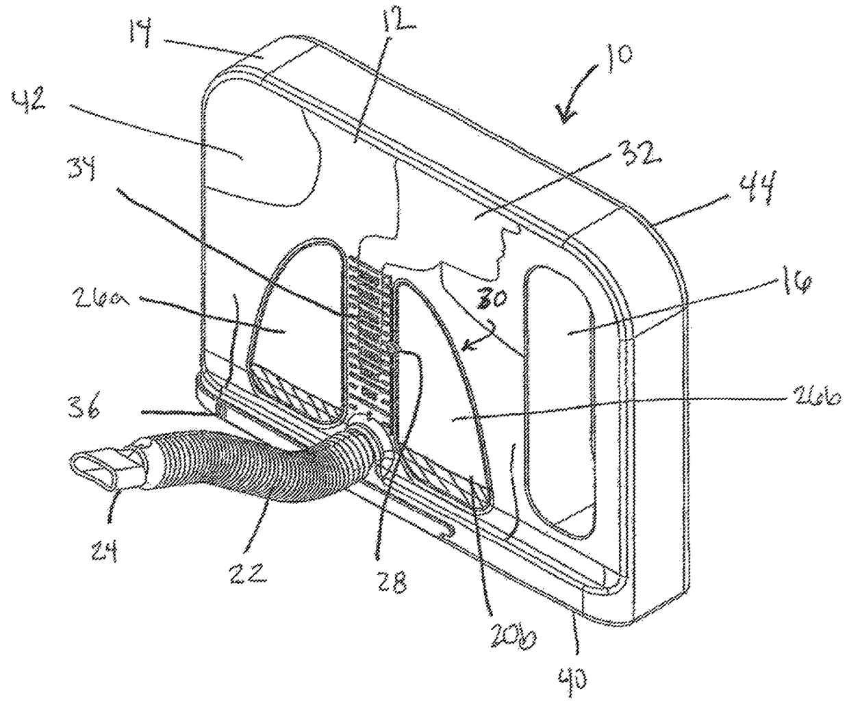
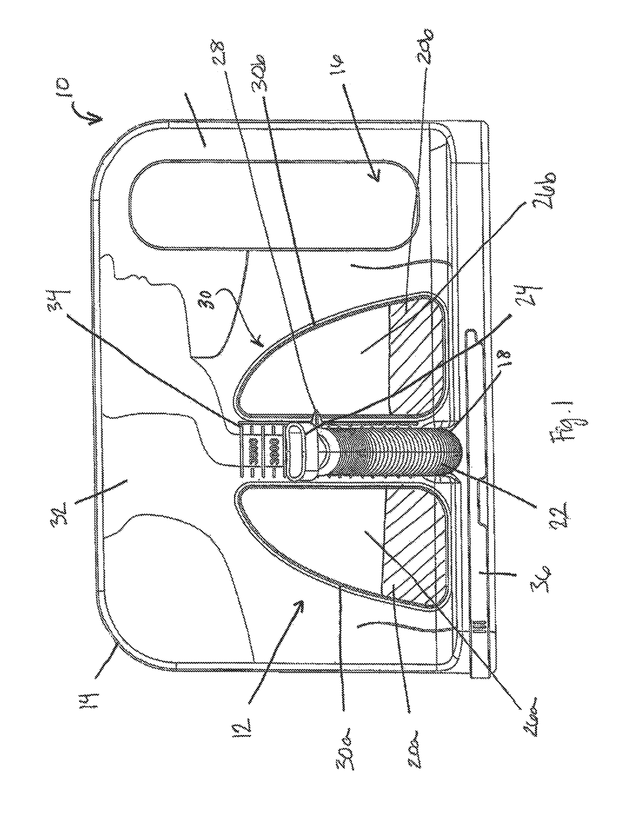
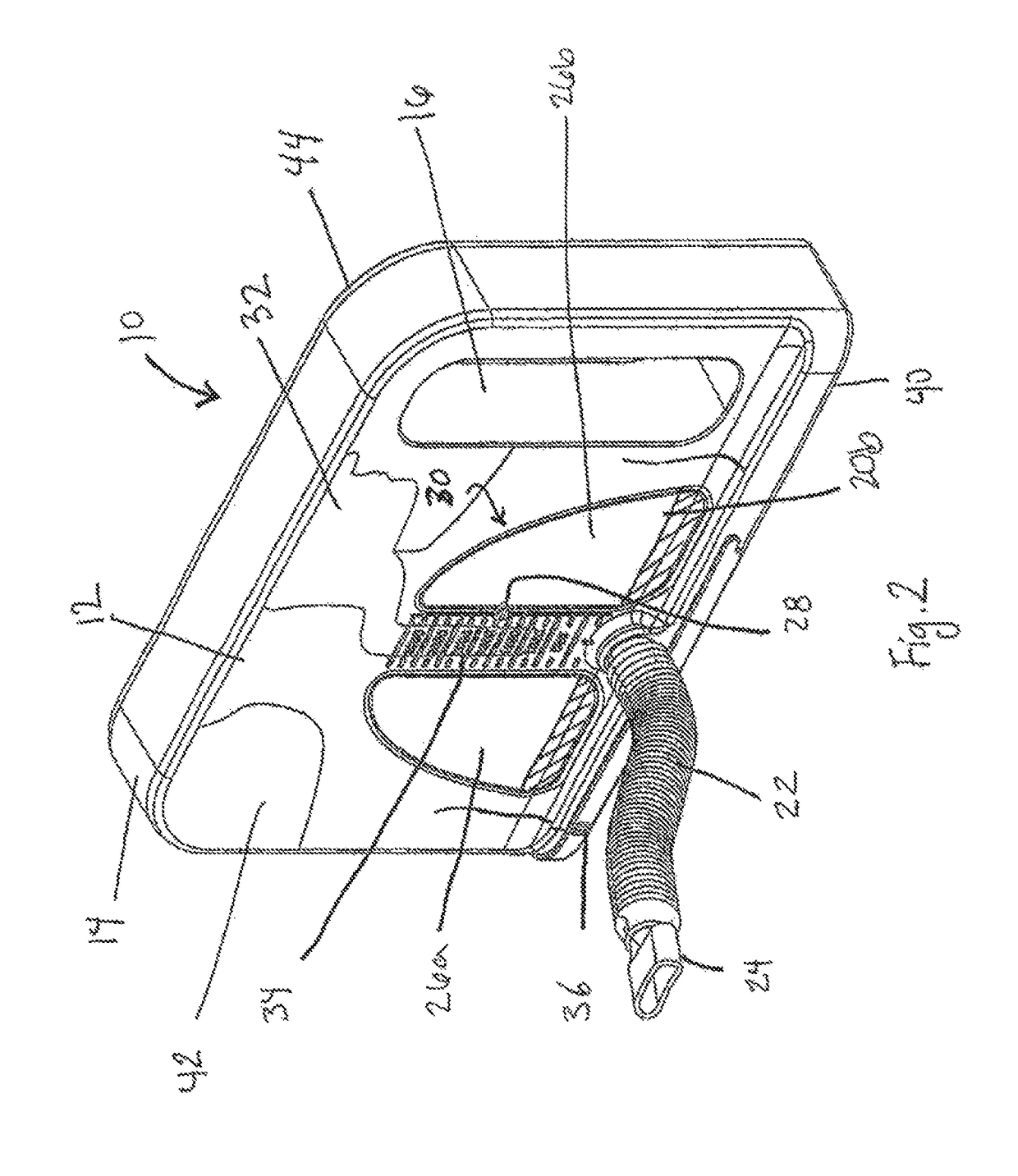
[0019]Referring now to the figures, FIGS. 1 and 2 illustrate one example embodiment of a spirometer device 10 that includes a housing 14 having a base 40, front wall 42, and back wall 44. Front wall 42 comprises a dis...


PUM


Abstract

A spirometer-type device is described that is designed to improve patient compliance with therapeutic breathing for improved pulmonary function. In an example embodiment, a display of human lungs is provided that visually elevate with inhalation. A patient's progress is visualized with a featured conspicuous level marker and upward motions of lungs that are seen from both sides of the device.

Description

CLAIM OF PRIORITY[0001]This application claims the benefit of and priority to U.S. Provisional Patent Application No. 61 / 764,397, filed Feb. 13, 2013 and titled “SPIROMETER DEVICE WITH VISUAL AID FOR THERAPEUTIC BREATHING” which application is incorporated herein by reference in its entirety.FIELD OF THE INVENTION[0002]The invention relates generally to a spirometer with a visual aid that assists in therapeutic breathing.BACKGROUND OF THE INVENTION[0003]Spirometers are generally devices used by physicians and medical professionals to gauge lung and breathing performance of patients that may have asthma, COPD or other breathing ailments, and patients recovering from surgery. When readings on the spirometers change, the therapy or medication may change. A change in spirometer readings may even prompt the patient to call a doctor or nurse for advice. Unfortunately, at times early detection of deteriorating breathing problems is not possible, which could avoid trips to the emergency roo...

Claims


Application Information

Patent Timeline
Patent Type & Authority Patents(United States)
IPC IPC(8): A61M16/00A61B5/093A63B23/18A61B5/091A61B5/00A63B71/06
CPCA61M16/0051A61B5/091A61B5/093A61B5/744A63B23/18A63B2071/0602A63B2071/0647A63B2225/62
Inventor MEYERS, JESSICA
Owner MEYERS JESSICA
Why Eureka
Try Eureka