Surface roughening apparatus for metal stock and surface roughening method for metal stock

a surface roughening and metal stock technology, applied in lighting and heating apparatus, forging/hammering/pressing machines, shape tools, etc., can solve the problems of increasing equipment costs, increasing manufacturing costs, and difficult to obtain sufficient bonding strength, so as to improve bonding strength and efficiently roughen the surface of metal stock

Active Publication Date: 2017-09-26
TOYOTA JIDOSHA KK
View PDF10 Cites 1 Cited by
  • Summary
  • Abstract
  • Description
  • Claims
  • Application Information

AI Technical Summary

Benefits of technology

[0009]The disclosure provides a surface roughening apparatus and a surface roughening method which are capable of roughening a surface of a metal stock more efficiently so as to increase a bonding strength.
[0012]When the height of each of the first protrusions is greater than the height of each of the second protrusions and when the tip angle of each of the first protrusions is smaller than the tip angle of each of the second protrusions, each of the recesses can be formed into an undercut shape after the metal stock is plastically deformed by pressing using the second mold. With the method in which the metal stock is pressed (press work) using the first mold having the plurality of first protrusions formed thereon and the metal stock is pressed (press work) using the second mold having the plurality of second protrusions formed thereon, a plurality of portions can be formed into an undercut shape all at once by the two pressing steps, and thus the work can be completed in a short period of time. Therefore, it is possible to roughen the surface of the metal stock more efficiently so as to increase the bonding strength.
[0014]With this structure, approximately uniform undercut shapes are formed in the respective recesses. The formation of approximately uniform undercut shapes makes it possible to improve the bonding strength. Undercut shapes for further improving the bonding strength thus can be formed more reliably.
[0017]According to the disclosed embodiments, it is possible to provide a surface roughening apparatus and a surface roughening method which are capable of roughening a surface of a metal stock more efficiently so as to increase a bonding strength.

Problems solved by technology

However, in the method using a laser, an increase in processing time and an increase in equipment cost cause an increase in manufacturing cost.
In the method using etching and the method using shot blasting, convex and concave portions formed on the surface of the metallic material have a small depth, which may make it difficult to obtain a sufficient bonding strength.
In such a structure, each ridge is plastically deformed by the roller at only one location, which results in an increase in the processing time for forming undercuts in all the grooves.

Method used


Image

  • Surface roughening apparatus for metal stock and surface roughening method for metal stock
  • Surface roughening apparatus for metal stock and surface roughening method for metal stock
  • Surface roughening apparatus for metal stock and surface roughening method for metal stock

Examples


first exemplary embodiment

(First Exemplary Embodiment)

[0039]Exemplary embodiments will be described below with reference to the drawings. The same elements are denoted by the same reference numerals throughout the drawings, and repeated descriptions thereof are omitted as appropriate.

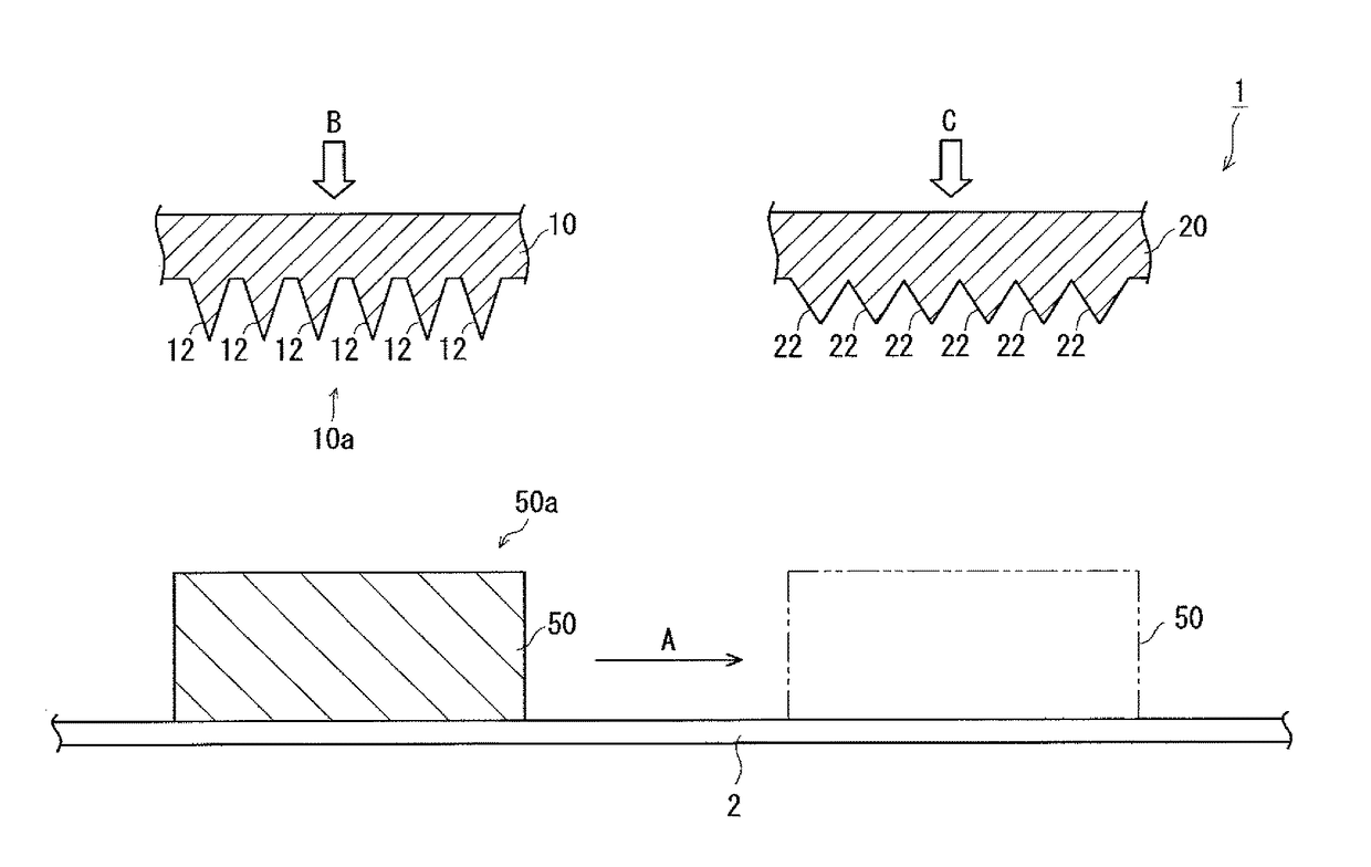
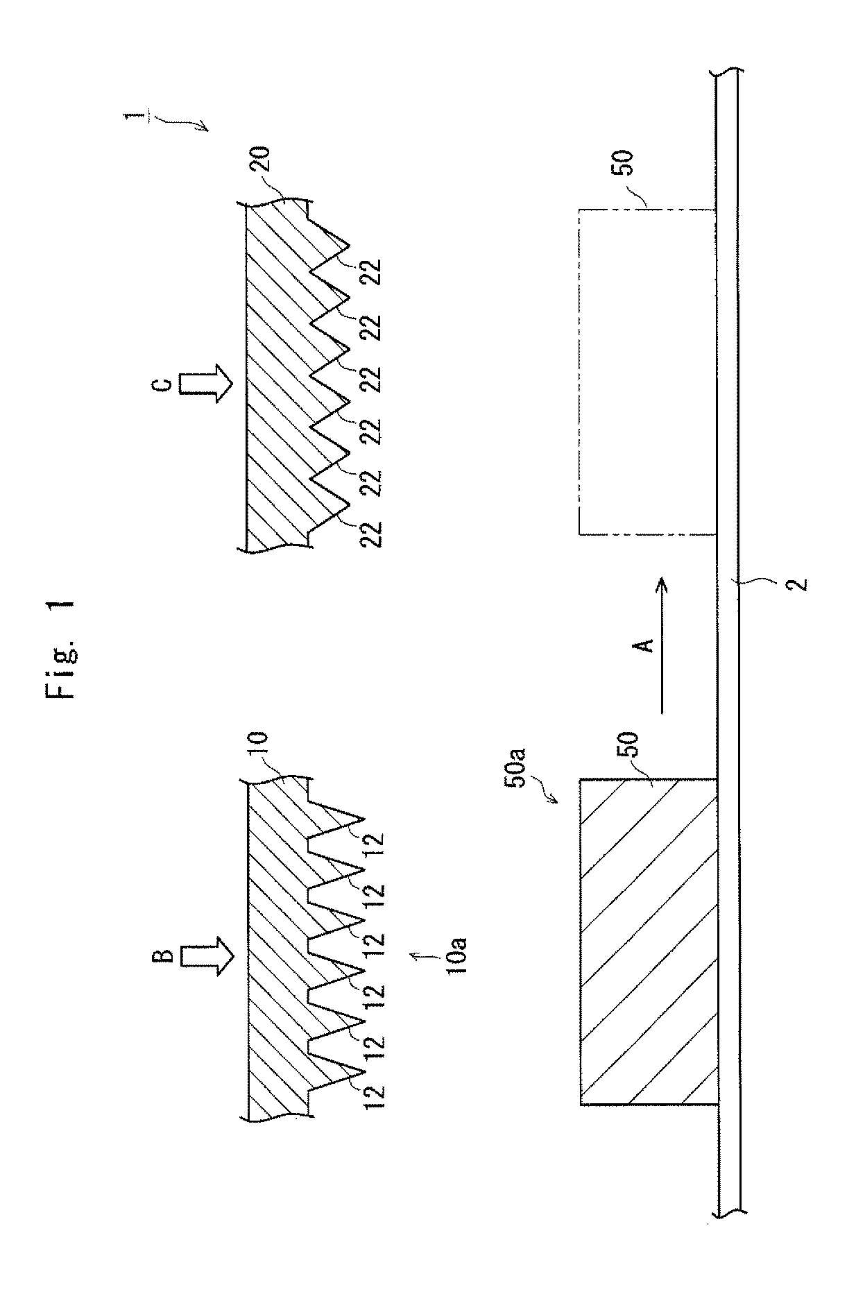
[0040]FIG. 1 is a diagram showing a surface roughening apparatus 1 according to a first exemplary embodiment. The surface roughening apparatus 1 includes a transport member 2, which transports a metallic material 50 (metal stock), a first mold 10 (first mold), and a second mold 20 (second mold). The transport member 2 transports the metallic material 50 to a location facing the first mold 10. As a result, an opposed surface 10a of the first mold 10 faces a surface 50a (first surface) of the metallic material 50. As indicated by an arrow A, the transport member 2 transports the metallic material 50 to a location facing the second mold 20. As a result, an opposed surface 20a of the second mold 20 faces the surface 50a of the metal...

second exemplary embodiment

(Second Exemplary Embodiment)

[0069]Next, a second exemplary embodiment will be described. In the second exemplary embodiment, the surface roughening method according to the first exemplary embodiment described above is applied to the formation of a pin-shaped fin (hereinafter referred to as a “pin fin”) which is formed in a cooler used for cooling electronic components and the like. Specifically, in the second exemplary embodiment, surface roughening of a metallic material is performed during the formation of a cooler made of a metallic material.

[0070]FIG. 11 is a diagram showing a method for producing an electronic device 70 according to the second exemplary embodiment. The electronic device 70 includes a plurality of electronic component structures 72. The electronic device 70 has a structure in which the plurality of electronic component structures 72 are joined together in a stacked state. Each electronic component structure 72 includes an electronic component 74, such as a powe...


PUM

PropertyMeasurementUnit
depthaaaaaaaaaa
shapeaaaaaaaaaa
heightaaaaaaaaaa

Abstract

A surface roughening apparatus includes a first mold and a second mold. The first mold has a plurality of first protrusions. The first mold presses a metallic material to form recesses corresponding to respective shapes of the first protrusions in a surface of the metallic material. The second mold has a plurality of second protrusions. After the first mold presses the metallic material, the second mold presses the metallic material, thereby deforming each recess into an undercut shape. A height of each first protrusion is greater than a height of each second protrusion. A tip angle of each first protrusion is smaller than a tip angle of each second protrusion.

Description

INCORPORATION BY REFERENCE[0001]This application is based upon and claims the benefit of priority from Japanese patent application No. 2015-139445, filed on Jul. 13, 2015, the disclosure of which is incorporated herein in its entirety by reference.BACKGROUND[0002]1. Technical Field[0003]The present disclosure relates to a surface roughening apparatus for a metal stock and a surface roughening method for a metal stock, and more particularly, to a surface roughening apparatus and a surface roughening method for roughening a surface of a metal stock.[0004]2. Description of Related Art[0005]It is known that in the case of bonding a metallic material and a resin to each other, the surface of the metallic material is roughened to increase the surface area, which leads to an improvement in bonding strength. Examples of the roughening method include methods using a laser, etching, and shot blasting. However, in the method using a laser, an increase in processing time and an increase in equi...

Claims


Application Information

Patent Timeline
Patent Type & Authority Patents(United States)
IPC IPC(8): B21K23/00B21J13/02B21D17/02B23P9/00
CPCB21K23/00B21D17/02B21J13/02B23P9/00B21D37/10B21D53/022F28F3/022F28F3/12F28F21/065H01L23/3677F28D2021/0028F28F2255/14
Inventor TOMIOKA, AKINORIINOSHITA, HIROFUMI
Owner TOYOTA JIDOSHA KK
Why Eureka
Try Eureka