Work machine, in particular dump truck or truck

a dump truck and work machine technology, applied in the field of work machines, can solve the problems of increased cabling effort, inability to start under load, and inability to operate with ideal efficiency in a very restricted speed range, so as to facilitate the movement of taken up functional modules, simplify installation work and disassembly, and facilitate access.

Active Publication Date: 2017-09-26
LIEBHERR MINING EQUIP COLMAR
View PDF57 Cites 6 Cited by
  • Summary
  • Abstract
  • Description
  • Claims
  • Application Information

AI Technical Summary

Benefits of technology

[0012]The at least one alternator, the power electronics and the at least one electric motor are particularly arranged behind one another at the vehicle in the direction of travel, optionally at the vehicle frame. Not only particularly short line paths thereby result between the electric motor and the power electronics, but also between the alternator and the power electronics. The already above-described advantages of the arrangement in accordance with the present disclosure are further optimized. An installation of the power electronics at least partially between the alternator and the driven driving axle is possible.
[0013]The vehicle frame typically comprises at least two frame beams which extend in parallel and which extend at least sectionally in parallel in the longitudinal direction of the vehicle. The power electronics can ideally be mounted between the two frame beams. The installation between the vehicle frame beams provides additional protection for the power electronics. In addition, this installation location is characterized by good service friendliness since the region is easily accessible from the ground and no other components of the work machine block access.
[0016]Further numerous installation possibilities for the individual functional modules of the power electronics are naturally conceivable which cannot be exclusively listed here. The gist of the present disclosure, however, comprises the distance of the power electronics, i.e. at least of some of the functional modules, from the alternator and / or from the driven driving axle being dimensioned as short as possible to achieve the advantages in accordance with the present disclosure.
[0018]It is conceivable for this purpose that one or more lifting gears are provided at the work machine, in particular in the region of the skip, particularly at the front lower edge of the skip, to be able to take up the power electronics or individual functional modules. A simple installation possibility or dismantling possibility for the power electronics or for individual components of the power electronics can be provided with the aid of the lifting gear. In addition to the vertical lifting movement, the lifting gear can additionally provide a horizontal movement of the load to be able to easily move the taken up functional modules.

Problems solved by technology

The reason for this process is that diesel engines, like all internal combustion engines, can only be operated with ideal efficiency in a very restricted speed range and cannot be started under load.
However, the long line paths increase the effort for the cabling.
The huge line length furthermore promotes the likelihood of electromagnetic interference, in particular between the power lines and the signal lines for transmitting the control signals to the alternator and to the electric motor.
Not only particularly short line paths thereby result between the electric motor and the power electronics, but also between the alternator and the power electronics.

Method used


Image

  • Work machine, in particular dump truck or truck
  • Work machine, in particular dump truck or truck
  • Work machine, in particular dump truck or truck

Examples


Embodiment Construction

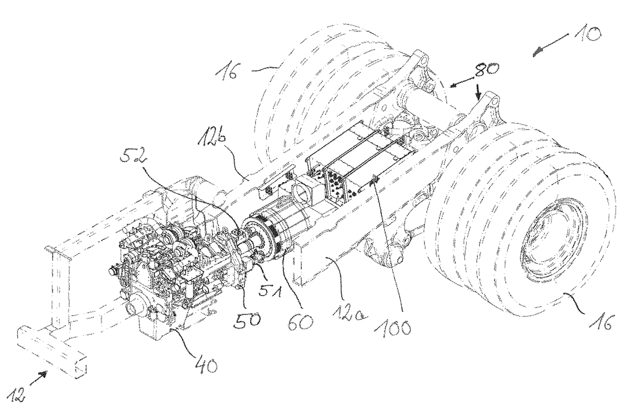
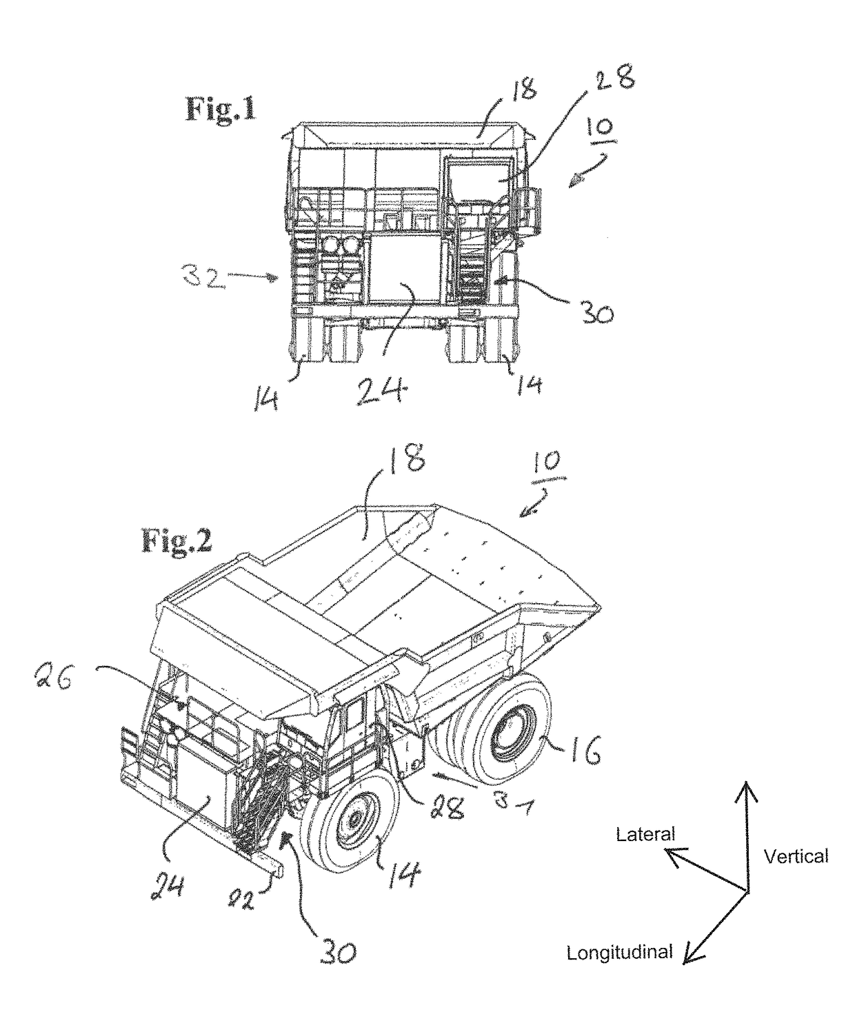
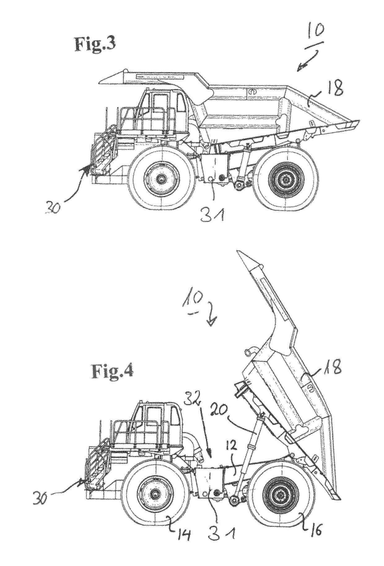
[0027]A dump truck 10 is shown in FIGS. 1 to 4. It is here a so-called large dump truck such as is used in ore mines. Front wheels 14 and rear wheels 16, driven via electric motors not shown in more detail, are supported at a rigid frame 12. The rear wheels 16 are designed with dual tires.

[0028]A skip 18 is pivotally connected to the frame 12 and is pivotable via hydraulic lifting cylinders 20 provided at both sides at the vehicle. The vehicle 10 is bounded by the bumper 22 in the region of the vehicle 10 at the front in the direction of travel. A radiator module 24 is arranged above the bumper 22. An upper deck 26 in turn extends over the width of the dump truck 10 above the radiator module 24. An operator's cabin 28 is arranged at a side of the upper deck 26. In the embodiment shown here, the operator's cabin 28 is positioned at the side of the upper deck 26 at the left in the direction of travel. The operator's cabin 28 thus lies above the front left wheel 14.

[0029]The dump truck...


PUM


Abstract

The present disclosure relates to a work machine, in particular in the form of a dump truck or of a truck, having a diesel electric traction drive, comprising at least one internal combustion engine, at least one alternator, at least one set of power electronics as well as at least one electric motor, wherein the power electronics are arranged at least partially in the region of a driven driving axle of the work machine.

Description

CROSS REFERENCE TO RELATED APPLICATION[0001]This application claims priority to German Patent Application No. 10 2014 003 203.5, entitled “Work Machine, In Particular Dump Truck or Truck” filed Mar. 6, 2014, which is hereby incorporated by reference in its entirety for all purposes.TECHNICAL FIELD[0002]The present disclosure relates to a work machine, in particular in the form of a dump truck or of a truck, having a diesel electric traction drive, comprising at least one internal combustion engine, at least one alternator, at least one set of power electronics as well as at least one electric motor.BACKGROUND AND SUMMARY[0003]Dump trucks or so-called large dump trucks are predominantly used in coal mining operations or ore mining operations for the transport of the mined coal, minerals and ores. These bulk material dumpers are manufactured in sizes of more than 90 metric tons (t) up to several 100 t in weight and payload so that they have very large dimensions overall.[0004]A diesel...

Claims


Application Information

Patent Timeline
Patent Type & Authority Patents(United States)
IPC IPC(8): B60R16/023B60K6/40B62D33/06B60S5/00B60P1/28B60K11/02B60K6/46B60K6/405B60K1/00B60L50/12
CPCB60R16/0239B60K6/40B60K6/405B60K6/46B60K11/02B60P1/28B60S5/00B62D33/0617B60K1/00B60Y2200/142B60Y2200/92Y02T10/6217Y10S903/951Y02T10/62B62D33/02
Inventor KUGELSTADT, KAILEVARAY, ADRIENRICHTHAMMER, BURKHARD
Owner LIEBHERR MINING EQUIP COLMAR
Why Eureka
Try Eureka