Passive mode carbon nanotube underwater acoustic transducer

a carbon nanotube, passive mode technology, applied in the direction of transducer details, electrical transducers, nanotechnology, etc., can solve the problems of inability to reciprocate thermo-acoustic process, inability to supply heat and shine light to the same electric bulb in order to generate electrical energy back, etc., to achieve better acoustic receiving sensitivity

Inactive Publication Date: 2017-10-03
UNITED STATES OF AMERICA
View PDF14 Cites 7 Cited by
  • Summary
  • Abstract
  • Description
  • Claims
  • Application Information

AI Technical Summary

Benefits of technology

[0024]It is a further object of the present invention to provide a passive acoustic transducer that can operate as an underwater acoustic hydrophone.
[0030]A still further difference and an advantage for the passive nanotube transducer; there is no need for a high temperature rated materials. Almost all types of water tight materials such as urethane can be used to seal the transducer housing. And also, for the passive carbon nanotube transducer; the electric impedance does not need to be below 100 Ohms or be set at 50 Ohms, in order to match power amplifier output electric impedances, to which are 50 Ohms for most commercial power equipment. Instead, to match preamplifier input electric impedance, the electric impedance is preferable high (several to hundreds of kilo-Ohms) for better acoustic receiving sensitivity for the passive acoustic nanotube transducer.

Problems solved by technology

Here, the energy flow is from electric to Joule heat, which is an irreversible process in that a reciprocal thermo-acoustic process becomes impossible by any active thermo-acoustic device.
The reciprocal (or reverse) of this process by supplying heat and shining light to the same electric bulb in order to generate electrical energy back is impossible, simply because Joule heat is involved.

Method used


Image

  • Passive mode carbon nanotube underwater acoustic transducer
  • Passive mode carbon nanotube underwater acoustic transducer

Examples


Embodiment Construction

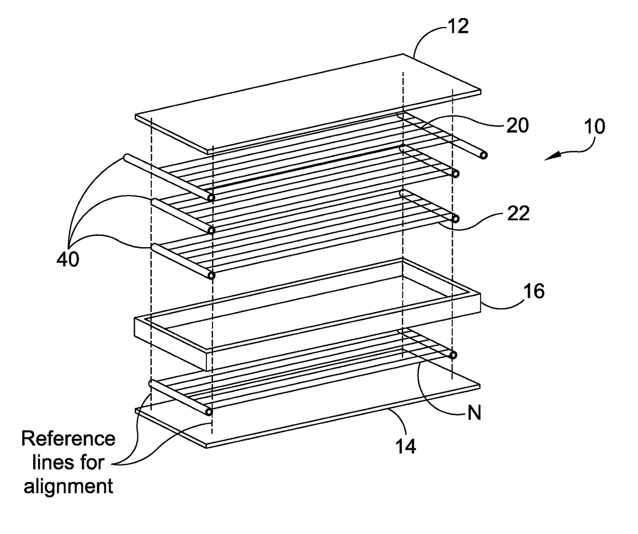
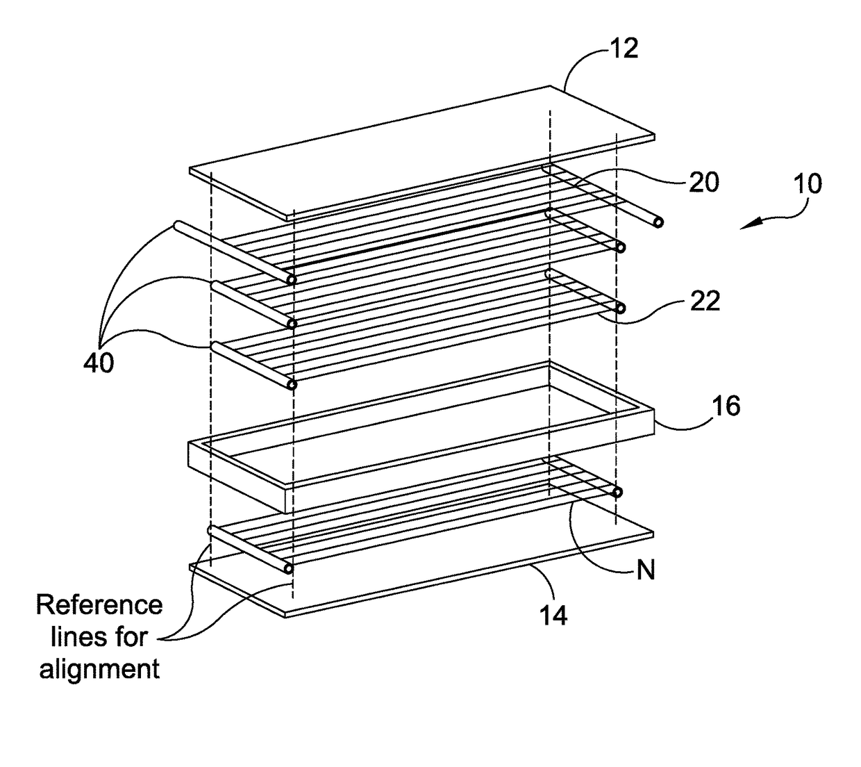
[0032]In the Figure, a multi-sheet carbon nanotube (CNT) material assembly or passive transducer 10 of the present invention is shown. The CNT transducer 10 comprises mechanical, acoustical and electrical sections.

[0033]The mechanical section includes a first shell 12 and a second shell 14. Unlike with the assembly of an active acoustic carbon nanotube material transducer that transmits; the shells of the passive transducer 10 do not have to be high temperature rated. As such, the first shell 12 and the second shell 14 can be made of urethane, mylar or plastic with the thickness of the shells based on known durability requirements as protective housing for the carbon nanotubes and acoustic receiving capabilities of the nanotubes but not for high temperature requirements. For example: the first (top) shell 12 and the second (bottom) shell 14 can be 0.005 inches to a 0.01 inch thick urethane sheet. The thicknesses of the top shell 12 and bottom shell 14 can vary.

[0034]Materials such a...


PUM

PropertyMeasurementUnit
thicknessaaaaaaaaaa
electric impedancesaaaaaaaaaa

Abstract

A passive carbon nanotube transducer is provided. The passive carbon nanotube transducer includes shells as protective walls for the top and bottom housing of the transducer with carbon nanotube sheets affixed between the shells. The shells act as acoustic windows that match the surrounding acoustic medium. A gasket encloses the shells and carbon nanotube sheets of the transducer. Each carbon nanotube sheet has an electrode at both ends. Multiple carbon nanotube sheets are capable of sensing sound induced environment temperature deviations and converting electric voltage or current for passive acoustic detection.

Description

STATEMENT OF GOVERNMENT INTEREST[0001]The invention described herein may be manufactured and used by or for the Government of the United States of America for governmental purposes without the payment of any royalties thereon or therefor.CROSS REFERENCE TO OTHER PATENT APPLICATIONS[0002]The present application relates to application Ser. No. 15 / 273,817; filed 23 Sep. 2016, entitled “A CARBON NANOTUBE UNDERWATER ACOUSTIC THERMOPHONE” and application Ser. No. 15 / 273,801; filed 23 Sep. 2016, “entitled “UNDERWATER ACOUSTIC CARBON NANOTUBE THERMOPHONE”.BACKGROUND OF THE INVENTION[0003](1) Field of the Invention[0004]The present invention is an acoustically transparent carbon nanotube transducer that can operate in a passive acoustic mode for data collection.[0005](2) Description of the Prior Art[0006]The principle of thermal active acoustic transduction is that when alternating current is passed through a comparatively thin transducer; periodic heating takes place in the conductor follow...

Claims


Application Information

Patent Timeline
Patent Type & Authority Patents(United States)
IPC IPC(8): H04R23/00H04R1/44B82Y15/00
CPCH04R1/44H04R23/002B82Y15/00H04R2307/023
Inventor HUANG, DEHUA
Owner UNITED STATES OF AMERICA
Why Eureka
Try Eureka