
Tri-chamber nutating pump

a nutating pump and chamber technology, applied in the direction of piston pumps, positive displacement liquid engines, pump components, etc., can solve the problems of inability to use a partial revolution, and inability to accurately dispense fluid from the nutating pump

Active Publication Date: 2017-10-10
FLUID MANAGEMENT LLC
View PDF16 Cites 0 Cited by
  • Summary
  • Abstract
  • Description
  • Claims
  • Application Information

AI Technical Summary

Benefits of technology

The patent describes a device called a compensating piston that helps to smooth out the output flow of a dual-chamber nutating pump. The device has two chambers that produce peaks and valleys in the output flow during a pump cycle. The compensating piston slides into a liner and is designed to retard the output flow during peaks and increase it during low points. The device helps to make the output flow more consistent and reduces leakage between the compensating piston and the liner.

Problems solved by technology

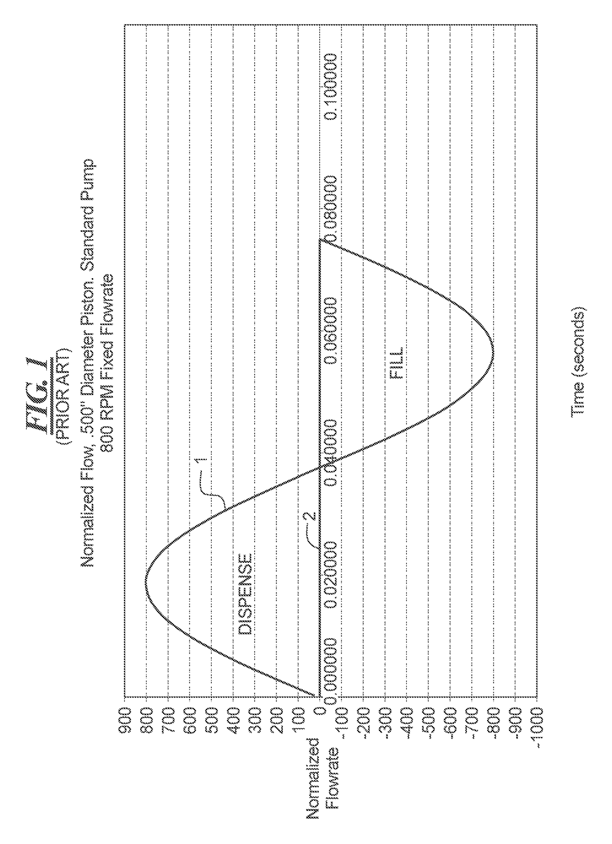
Further, because the output is not linear (see the line 1 of FIG. 1), some users limit the operation of conventional nutating pumps to complete 360° revolutions of the piston or at least one full dispense stroke.
However, this methodology often requires a user to choose between a small pump that requires multiple revolutions of the piston to dispense the required volume and a large pump that requires a partial revolution of the piston to dispense the required volume.
Further, the operator may also have to choose between running the motor of a small pump at high speeds to dispense larger volumes and running the motor of a large pump at slow or minimum speeds for smaller volumes.
While using a partial revolution to accurately dispense fluid from a nutating pump is difficult due to the non-linear output of the nutating pump dispense profile (i.e., see FIG. 1), controllers, software algorithms and sensors can be used to monitor the angular position of the piston.
While operating the nutating pump at a constant motor speed has its benefits in terms of simplicity of controller design and pump operation, the use of a constant motor speed has inherent disadvantages.
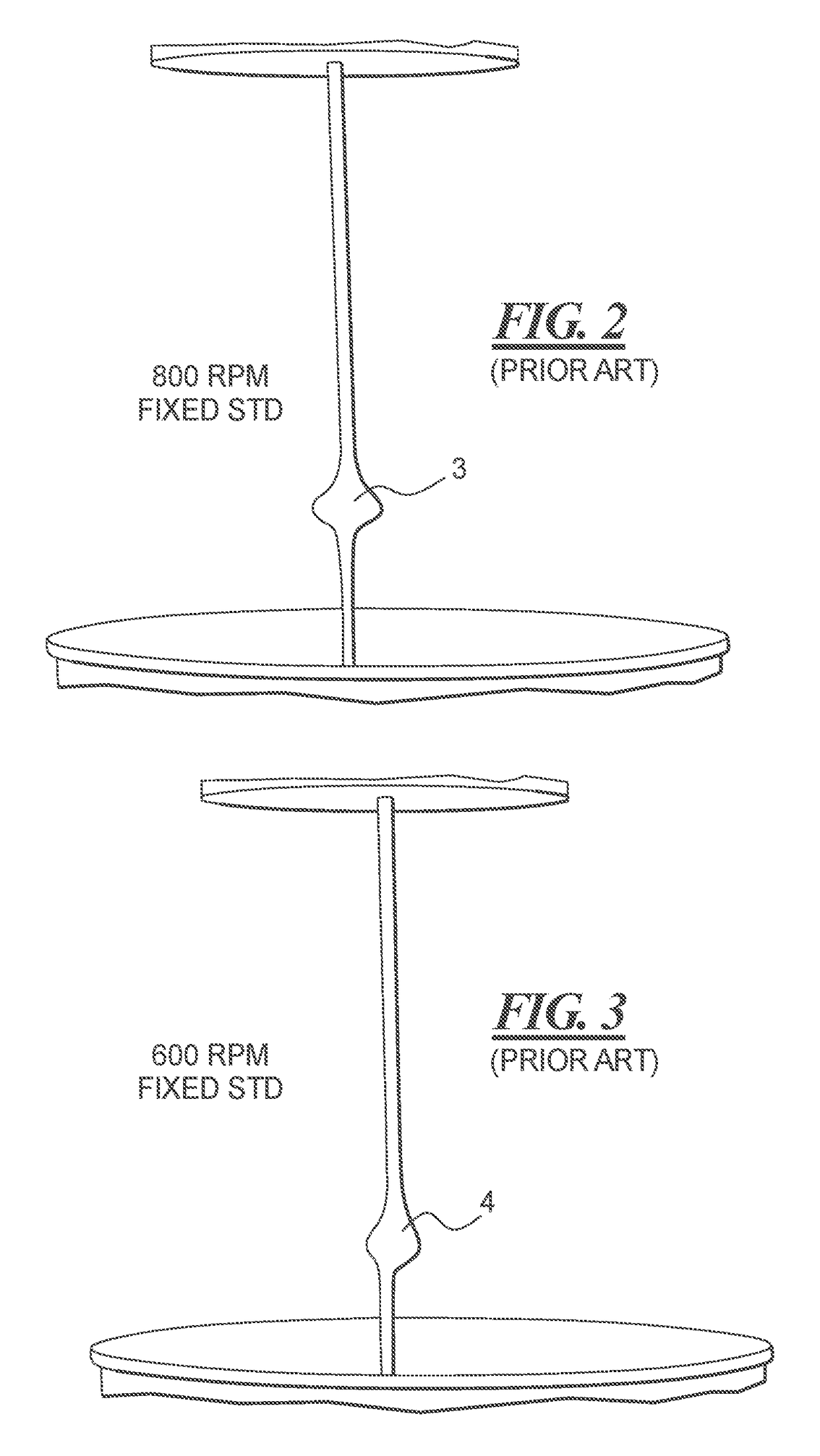
Specifically, in certain applications, the maximum output flow rate illustrated on the left side of FIG. 1 can be disadvantageous because the output fluid may splash or splatter as the fluid is pumped into the output receptacle at the higher flow rates.
For example, in paint or cosmetics dispensing applications, any splashing of the colorant as it is being pumped into the output container results in an inaccurate dispense as well as colorant being splashed on the machine, which requires labor-intensive clean up and maintenance.
This splashing problem will adversely affect any nutating pump application where precise amounts of output fluid are being delivered to small receptacles or to output receptacles that are either full or partially full of liquid.
To avoid splashing altogether, the motor speed would have to be reduced more than 20% thereby making the choice of a nutating pump less attractive despite its high accuracy.
A further disadvantage to the sinusoidal profile of FIG. 1 is an accompanying pressure spike that causes an increase in motor torque.
Specifically, the large pressure drop that occurs within a nutating pump as the piston rotates from the point where the dispense rate is at a maximum to the point where the intake rate is at a maximum (i.e. the peak of the curve shown at the left in FIG. 1 to the valley of the curve shown towards the right in FIG. 1) can result in motor stalling for those systems where the motor is operated at a constant speed.
Motor stalling will result in an inconsistent or non-constant motor speed, thereby affecting the sinusoidal dispense rate profile illustrated in FIG. 1 and any control system or control method based upon a preprogrammed sinusoidal dispense profile.
The stalling problem will occur on the intake side of FIG. 1 as well as when the pump goes from the maximum intake flow rate to the maximum dispense flow rate.
However, the nutating pump design of U.S. Pat. No. 6,749,402 as shown in FIG. 4, while reducing splashing, still results in a start / stop dispense profile and therefore the dispense is not a pulsation-free or a steady, smooth flow.
Further, the abrupt starting and stopping of the dispensing followed by a significant lag time during the fill portion of the cycle still presents the problems of significant pressure spikes and gaps in the fluid stream exiting the dispense nozzle.
However, the dual-chamber pump 20 of FIGS. 5-7, despite the improvements, can create pulsations, which can lead to splashing and inaccurate dispenses.

Method used


Image

  • Tri-chamber nutating pump
  • Tri-chamber nutating pump
  • Tri-chamber nutating pump

Examples


Embodiment Construction

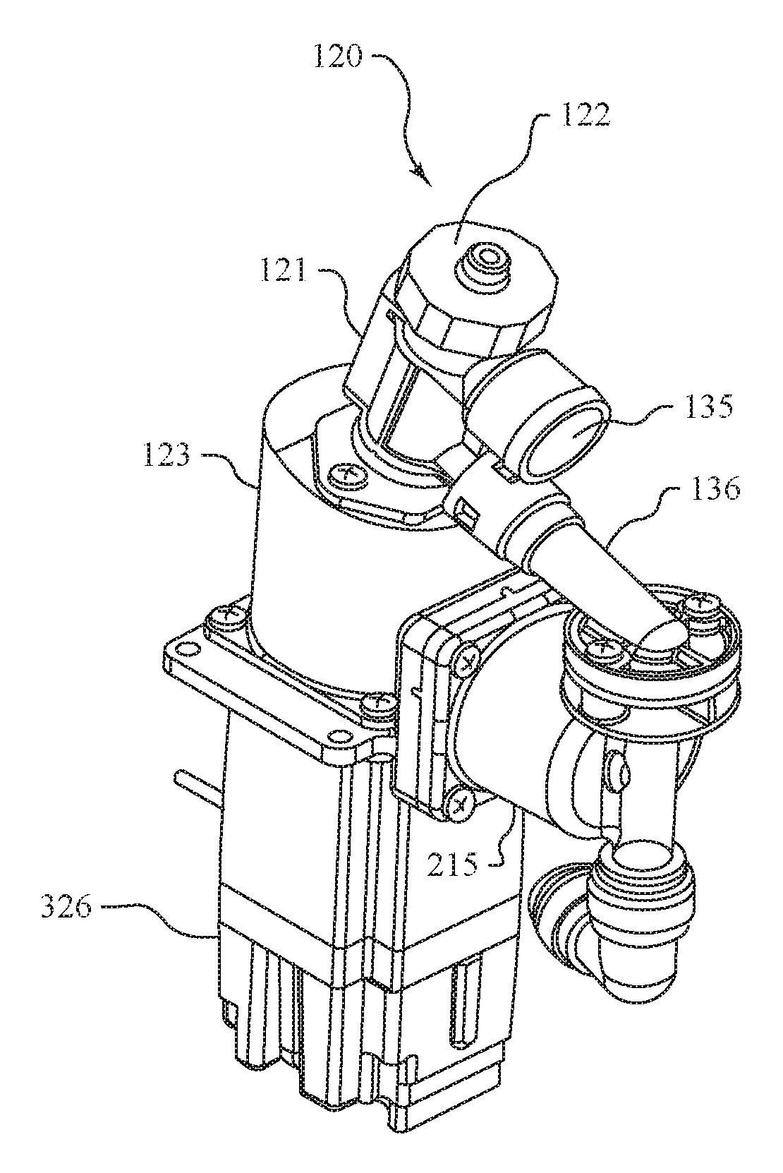
[0057]A nutating pump 120 is illustrated in FIGS. 8-9. The nutating pump 120 includes the basic features of the nutating pump as shown in FIGS. 5-6 and these features are identified using the reference numerals of FIGS. 5-6 with the prefix “1”, e.g., the pump housing 121 as opposed to the pump housing “21”. The nutating pump 120 includes a pump housing 121 that is coupled to an enclosure 122. The nutating pump 120 also includes an intermediate housing 123, which encloses the coupling 124, the proximal end 126 of the nutating piston 110 and the cam 201, which is also illustrated in FIGS. 22-23.

[0058]The intermediate housing 123 also encloses a shroud 202, which provides dust protection for the various mechanical components disposed in the intermediate housing 123. The shroud 202 is utilized because the nutating pump 120 may be used to dispense colorants. For example, tints or colorants used to add color the white base material of a paint mixture can generate dust if the solvent evapo...


PUM


Abstract

A tri-chamber nutating pump is disclosed which includes two pump chambers disposed within a pump housing that accommodates a nutating piston. A reciprocating compensating piston is also provided with its own compensating housing that is connected to the outlet. As a cumulative output from the first two pump chambers reaches its maximum level, the compensating piston is pushed into the outlet or through a passage to reduce the output of the first two chambers and avoid splashing. As the output from the first two chambers reaches its minimum level, the compensating piston is withdrawn from the outlet or through a passage thereby increasing the output of the third chamber to its maximum level when the output from the first two pump chambers reaches its minimum level.

Description

CROSS-REFERENCE TO RELATED APPLICATIONS[0001]This application is a 35 U.S.C §371 U.S. national stage filing of International Patent Application No. PCT / US14 / 47369 filed on Jul. 21, 2014, which claims priority under the Paris Convention and 35 U.S.C §120 to U.S. Provisional Patent Application No. 61 / 856,274, filed on Jul. 19, 2013.FIELD OF THE DISCLOSURE[0002]Improved nutating pumps are disclosed with a third chamber added to the dual-chamber pump of U.S. Pat. No. 7,946,832, which is incorporated herewith. The third chamber is disposed adjacent to a compensating piston, or other actively driven displacement device, which provides a cyclic displacement (zero net flow through the cycle), which compensates for pulsations in output flow the dual-chamber pump of U.S. Pat. No. 7,946,832. The disclosed pumps also provide a more steady flow than the four chamber pump disclosed in U.S. Pat. No. 8,353,690, which is also incorporated herewith. The disclosed tri-chamber pumps provide an output f...

Claims


Application Information

Patent Timeline
Patent Type & Authority Patents(United States)
IPC IPC(8): F04B11/00F04B7/06
CPCF04B7/06F04B11/0075
Inventor HOGAN, TIM PATRICK
Owner FLUID MANAGEMENT LLC
Learn More