
Pattern formation method

Inactive Publication Date: 2005-06-07
PANASONIC CORP
View PDF5 Cites 0 Cited by
  • Summary
  • Abstract
  • Description
  • Claims
  • Application Information

AI Technical Summary

Benefits of technology

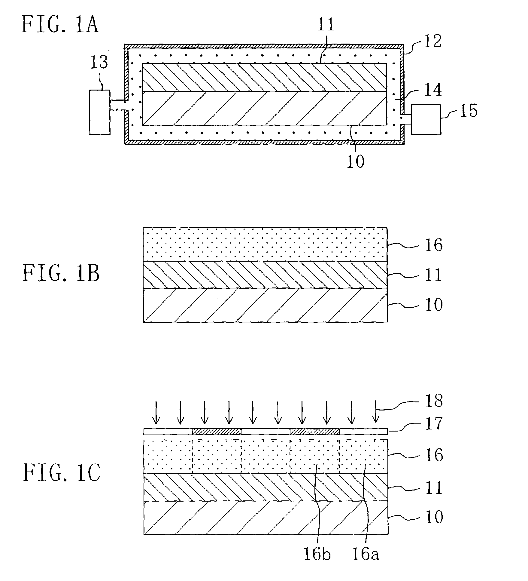
[0017]Accordingly, examination has been made on means for preventing the acid generated in the exposed portion of the resist film from being incorporated in the pores or the recesses of the underlying film. As a result, it has been found that when the underlying film is treated in a supercritical fluid, the surface of the underlying film is flattened, namely, the pores or the recesses of the underlying film are reduced, and therefore, the amount of acid incorporated in the underlying film can be reduced.
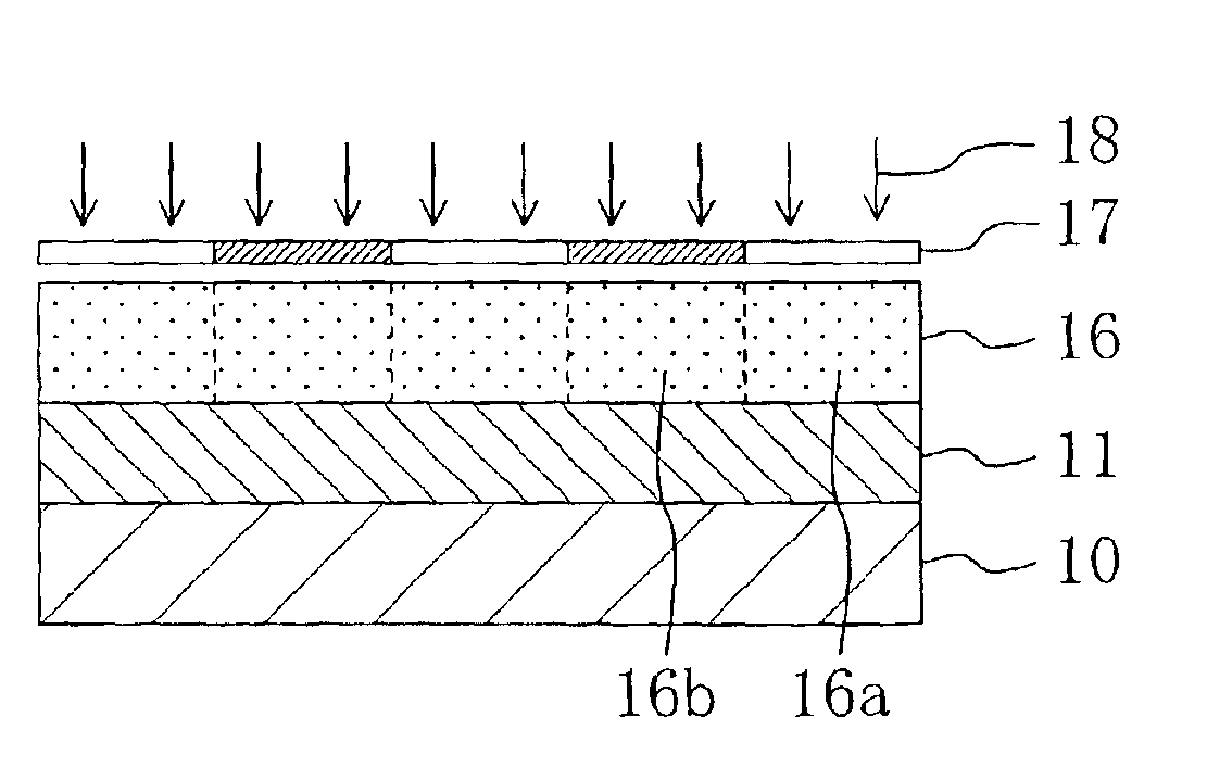
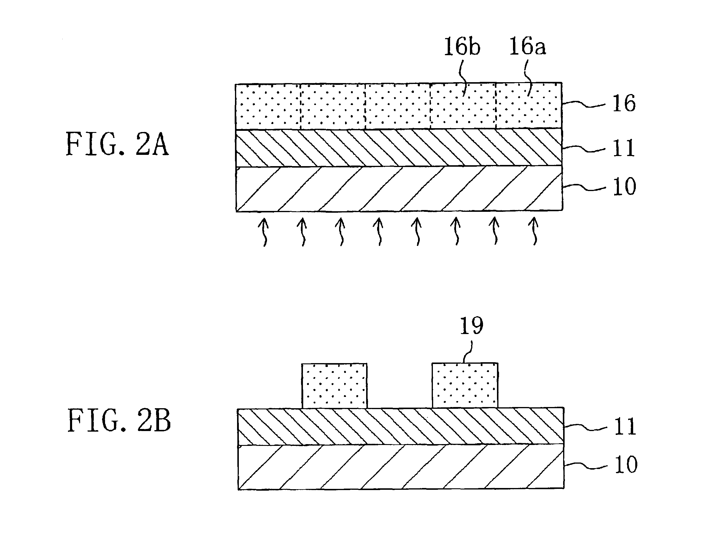
[0020]In the pattern formation method of this invention, after flattening the surface of the underlying film having pores or including an organic material through a treatment performed in a supercritical fluid, namely, after reducing pores or recesses on the underlying film, the resist film made of the chemically amplified resist material is formed on the underlying film. Therefore, an acid generated in an exposed portion of the resist film is minimally incorporated in the pores or the recesses of the underlying film. Accordingly, a catalytic reaction of the acid is not reduced at the bottom of the exposed portion of the resist film. As a result, a footing shape of a positive resist pattern and an undercut shape of a negative resist pattern can be suppressed, so as to form a resist pattern in a good cross-sectional shape.
[0029]Also, since the supercritical fluid placed in a subcritical state that has been used for flattening the surface of the underlying film is changed to a supercritical fluid placed in a supercritical state by heating and then is restored to a fluid in a general state by reducing a pressure. Therefore, a supercritical fluid in a fluid state and a supercritical fluid in a gas state are never present at the same time, so that the surface treatment of the underlying film can be efficiently carried out.
[0031]Thus, the surface of the underlying film can be easily flattened.
[0033]Thus, the supercritical fluid can be easily and definitely obtained.
[0035]Thus, the surface material that has been replaced with the supercritical fluid and is dissolved in the supercritical fluid is discharged to the outside together with the flowing supercritical fluid, so that the surface of the underlying film can be efficiently flattened.

Problems solved by technology

As a result, it has been found that in the case where an underlying film has pores or includes an organic material, the shape of a resultant resist pattern formed thereon becomes defective.
As a result, the amount of acid is so insufficient at the bottom of the exposed portion of the resist film that a catalytic reaction of the acid cannot be sufficiently carried out.
Therefore, solubility in a developer is spoiled at the bottom of the exposed portion of a positive resist film or insolubility in a developer is spoiled at the bottom of the exposed portion of a negative resist film.
As a result, the positive resist pattern is in a defective footing shape and the negative resist pattern is in a defective undercut shape.

Method used


Image

  • Pattern formation method
  • Pattern formation method
  • Pattern formation method

Examples


embodiment 1

Modification of Embodiment 1

[0059]A pattern formation method according to a modification of Embodiment 1 will now be described. This modification is different from Embodiment 1 in the chemically amplified resist material alone, and hence, the chemically amplified resist material alone will be herein described. Specifically, the chemically amplified resist material used in the modification has the following composition:

[0060]

Base polymer: poly((2-methyl-2-adamantyl acrylate) −  2 g(γ-butyrolactone methacrylate)) (wherein 2-methyl-2-adamantylacrylate:γ-butyrolactone methacrylate = 70 mol %:30 mol %)Acid generator: naphthaleneimino tosylate0.04 gSolvent: propylene glycol monomethyl ether acetate  20 g

[0061]In this chemically amplified resist material, the base polymer has an adamantyl group as an acid labile group of an ester group. Instead, the base polymer may have a t-butyl group or a t-butyloxycarbonyl group.

[0062]Also, in the chemically amplified resist material, naphthaleneimino ...

embodiment 2

[0064]A pattern formation method according to Embodiment 2 of the invention will now be described with reference to FIGS. 3A through 3C, 4A and 4B.

[0065]First, siloxane doped with carbon atoms (with a dielectric constant of 2.5) is deposited on a substrate 20, so as to form a low dielectric insulating film 21 corresponding to an underlying film to be treated. Thus, the low dielectric insulating film 21 is made of carbon-containing siloxane, and therefore, the low dielectric insulating film 21 has a rough surface.

[0066]Then, the low dielectric insulating film 21 is placed in a chamber 22. Thereafter, the low dielectric insulating film 21 is subjected to a surface flattening treatment with a supercritical fluid 23 of carbon dioxide (CO2) (which is placed in a subcritical state by being kept at a temperature of 20° C. and at 80 atmospheric pressure) for 30 minutes.

[0067]In this manner, in the chamber 22, a material of recesses of the rough surface of the low dielectric insulating film ...


PUM


Abstract

After flattening a surface of an underlying film that has pores or includes an organic material by treating the underlying film in a supercritical fluid, a resist film made of a chemically amplified resist material is formed on the underlying film whose surface has been flattened. Next, pattern exposure is performed by selectively irradiating the resist film with exposing light, and then, the resist film is developed after the pattern exposure, so as to form a resist pattern.

Description

BACKGROUND OF THE INVENTION[0001]The present invention relates to a pattern formation method for use in fabrication processing or the like for a semiconductor integrated circuit device.[0002]In the fabrication processing for a semiconductor integrated circuit device or the like, the size of a resist pattern (pattern width) formed by lithography technique is further refined in accordance with increase in the degree of integration of semiconductor integrated circuits, and accordingly, the aspect ratio of a resist pattern is remarkably increasing.[0003]Also, the dielectric constant of an insulating film is desired to be further lowered in accordance with improved performance of semiconductor devices. Therefore, use of a low dielectric insulating film that has a lower dielectric constant than a generally used silicon oxide film, such as an insulating film having pores or including an organic material, has been proposed.[0004]Now, a conventional pattern formation method will be described...

Claims


Application Information

Patent Timeline
IPC IPC(8): H01L21/02H01L21/027H01L21/3105H01L21/311G03F7/039G03F7/004G03F7/16G03F7/26G03F7/38
CPCG03F7/16H01L21/31144H01L21/31055H01L21/31058H01L21/0271G03F7/0045
Inventor ENDO, MASAYUKISASAGO, MASARU
Owner PANASONIC CORP
Learn More