
Cross-shaped infrared polarized light bridge based on photonic crystal waveguide

photonic crystal waveguide technology, applied in the field of microoptical polarized light bridges, can solve the problems of inability to design a polarized light bridge, inability to use light path integration, and two methods that cannot be used for designing conventional polarizing devices, etc., to achieve small structural volume, high light transmission efficiency, and suitable for large-scale light path integration

Inactive Publication Date: 2017-10-10
SHENZHEN UNIV
View PDF4 Cites 0 Cited by
  • Summary
  • Abstract
  • Description
  • Claims
  • Application Information

AI Technical Summary

Benefits of technology

[0004]The objective of the present invention is to overcome shortages in the prior art, and provide a cross-shaped infrared polarized light bridge based on a photonic crystal, which is small in structural volume, high in degree of polarization, convenient for integration and highly efficient.
[0016]The present invention has the following advantages compared with the prior art:
[0017]1. The cross-shaped infrared polarized light bridge based on the photonic crystal waveguide is small in structural volume, high in light transmission efficiency, and suitable for large-scale light path integration.
[0018]2. The TE light wave signal and the TM light wave signal can be efficiently subjected to directional conduction in a short range, and crosstalk is not caused at the intersection position of the cross-shaped light bridge.
[0019]3. The function of directional conduction for the polarized light waves can be realized through four point defects in a short range, thus integration is facilitated and high efficiency is achieved.
[0020]4. Compared with other polarization splitting devices adopting a coupled-cavity mode, the device has a quite high extinction ratio, a high degree of polarization, an extremely low insertion loss and a wide operating wavelength range, and can allow pulses with certain spectral widths or Gaussian lights or lights with different wavelengths to work, or allow lights with a plurality of wavelengths to work simultaneously.

Problems solved by technology

The traditional light bridges and polarized light bridges are relatively large in volume and cannot be used in light path integration because of applying a geometric optical principle.
The two methods can only be used for designing conventional polarizing devices, but cannot be used for designing a polarized light bridge by applying the characteristics of the two methods, wherein the polarized light bridge is a device capable of allowing optical signals with different polarization states to be subjected to intersection conduction without mutual influence at the position of a waveguide junction.

Method used


Image

  • Cross-shaped infrared polarized light bridge based on photonic crystal waveguide
  • Cross-shaped infrared polarized light bridge based on photonic crystal waveguide
  • Cross-shaped infrared polarized light bridge based on photonic crystal waveguide

Examples


Embodiment Construction

[0035]The present invention will be further elaborated below in detail with reference to the accompanying drawings and embodiments:

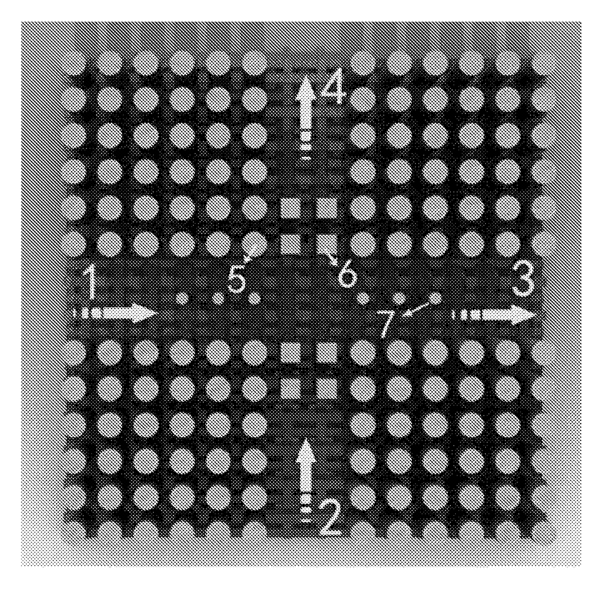
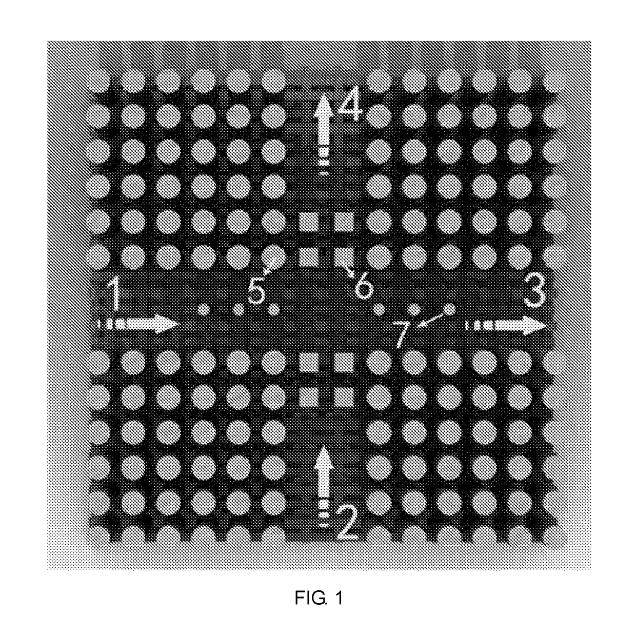
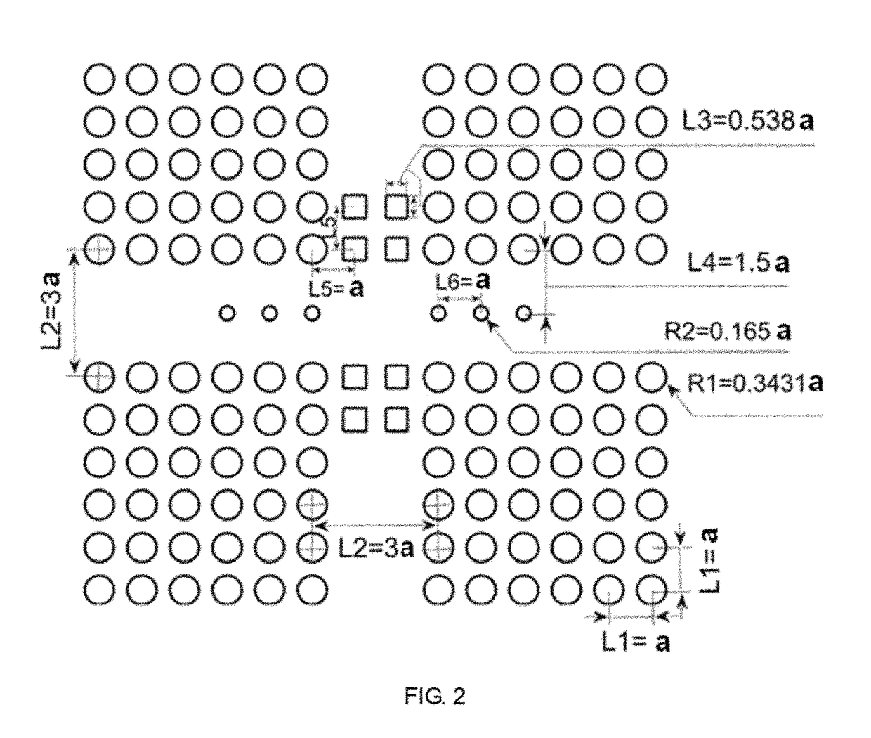
[0036]As shown in FIG. 1, the cross-shaped infrared polarized light bridge based on the photonic crystal waveguide of the present invention comprises a photonic crystal waveguide provided with a complete bandgap, wherein the photonic crystal waveguide is in a cross shape, waveguide defect dielectric cylinders are arranged in the photonic crystal cross-shaped waveguide, and the waveguide defect dielectric cylinders are square defect dielectric cylinders and round defect dielectric cylinders; and the photonic crystal cross-shaped waveguide is composed of a vertical TE waveguide, a horizontal TM waveguide, a TM optical signal input port, a TM output port, a TE optical signal input port and a TE output port. Initial signal lights of the device enter from the left port 1 and the lower port 2, a TE light wave outputs from the upper port 4, and a TM light wave ...


PUM


Abstract

A cross-shaped infrared polarized light bridge based on a photonic crystal waveguide. The present invention aims to provide a polarized light bridge that is small in structural size, high in polarization degree, convenient to integrate, and highly efficient, besides which, crosstalk is not caused at a cross intersection. The cross-shaped infrared polarized light bridge comprises a photonic crystal waveguide provided with a complete bandgap. The photonic crystal waveguide is in a cross shape. Waveguide defect dielectric columns are disposed in the photonic crystal cross-shaped waveguide. The waveguide defect dielectric columns are square defect dielectric columns (6) and round defect dielectric columns (7). The photonic crystal cross-shaped waveguide comprises a vertical TE waveguide, a horizontal TM waveguide, a TM optical signal input port (1), a TM output port (3), a TE optical signal input port (2), and a TE output port (4). The two input ports (1,2) of the photonic crystal waveguide separately input a TM optical signal and a TE optical signal. Mutual influence is not caused at a cross intersection position of light circuits formed by the TM wave and the TE wave in a shared central area. The input TM optical signal is output from the TM output port (3). The input TE optical signal is output from the TE output port (4).

Description

CROSS-REFERENCE TO RELATED APPLICATIONS[0001]This application is a continuation of International Patent Application No. PCT / CN2015 / 074384 with a filing date of Mar. 17, 2015, designating the United States, now pending, and further claims priority to Chinese Patent Application No. 201410108216.X with a filing date of Mar. 21, 2014. The content of the aforementioned applications, including any intervening amendments thereto, are incorporated herein by reference.TECHNICAL FIELD[0002]The present invention relates to the field of micro-optical polarized light bridges, and particularly relates to a micro-optical polarized light bridge based on a photonic crystal technology.BACKGROUND OF THE PRESENT INVENTION[0003]The traditional light bridges and polarized light bridges are relatively large in volume and cannot be used in light path integration because of applying a geometric optical principle. Micro devices including polarized light bridges can be produced on the basis of photonic crysta...

Claims


Application Information

Patent Timeline
Patent Type & Authority Patents(United States)
IPC IPC(8): G02B6/12G02B6/122G02B6/125G02B6/126
CPCG02B6/1225G02B6/126G02B6/125
Inventor OUYANG, ZHENGBIAOJIN, XINYU, QUANQIANG
Owner SHENZHEN UNIV
Learn More