Hydraulic drive system

a technology of hydraulic drive and drive shaft, which is applied in the direction of servomotors, servomotors, constructions, etc., can solve the problem that the hydraulic pump b>101/b> is not able to regenerate the potential energy of the working implement, and achieve the effect of suppressing the rise in hydraulic pressur

Inactive Publication Date: 2017-10-17
KOMATSU LTD
View PDF19 Cites 9 Cited by
  • Summary
  • Abstract
  • Description
  • Claims
  • Application Information

AI Technical Summary

Benefits of technology

[0009]For example, a case is assumed hereinbelow in which the hydraulic cylinder 103 is a boom cylinder and an operation for raising the boom is conducted. The pressure receiving area ratio between the first chamber 104 and the second chamber 105 is 2:1. In this case, a target discharge flow rate of the first hydraulic pump 101 and a target discharge flow rate of the second hydraulic pump 102 are set so that the ratio between the discharge flow rate of the first hydraulic pump 101 and the discharge flow rate of the second hydraulic pump 102 becomes 1:1. However, as illustrated in FIG. 12, the actual discharge flow rate of the first hydraulic pump 101 is “0.95” and the actual discharge flow rate of the second hydraulic pump 102 is “1.05.” In this case, hydraulic fluid at a flow rate of “2.0 (=0.95+1.05)” is supplied to the first chamber 104 of the hydraulic cylinder 103. Hydraulic fluid at a flow rate of “1.0” is exhausted from the second chamber 105. However, the first hydraulic pump 101 is only able to suck in hydraulic fluid at a flow rate of “0.95” because the discharge flow rate of the first hydraulic pump 101 is “0.95.” As a result, an excess flow rate corresponding to the difference between “1.0” and “0.95” is generated in the second flowpath 107. When the hydraulic pressure of the second flowpath 107 rises up to the relief pressure of a relief valve 108, the relief valve 108 is opened and the hydraulic fluid of the excess flow rate is exhausted to a charge circuit 109. Because the load applied to the hydraulic cylinder 103 during the raising operation of the boom acts on the hydraulic fluid in the first chamber 104, there is no need for the hydraulic pressure in the second flowpath 107 to rise. Therefore, the energy for raising the hydraulic fluid of the excess flow rate in the second flowpath 107 as described above is wasted energy. Moreover, the hydraulic pressure in the first flowpath 106 needs to be greater than the hydraulic pressure in the second flowpath 107 to expand the hydraulic cylinder 103. Therefore, the hydraulic pressure in the first flowpath 106 needs to be increased even more to be greater than the hydraulic pressure in the second flowpath 107. In this case, if the horsepower for driving the first hydraulic pump 101 and the second hydraulic pump 102 does not change, the flow rate of the hydraulic fluid discharged from the first hydraulic pump 101 and the second hydraulic pump 102 is reduced. As a result, the operation speed of the hydraulic cylinder 103 decreases and workability is reduced.
[0011]An object of the present invention is to provide a hydraulic drive system that is able to suppress a rise in hydraulic pressure even when a deviation in discharge flow rate control between hydraulic pumps occurs in a hydraulic circuit in which a closed circuit is configured between a hydraulic pump and a hydraulic cylinder.
[0017]When the hydraulic cylinder expands with resistance to an external force in the hydraulic drive system according to the first exemplary embodiment of the present invention, the shuttle valve allows communication between the second input port and the drain port. As a result, a rise in the hydraulic pressure in the second flowpath is suppressed even if the discharge flow rate of the first hydraulic pump is less than the discharge flow rate of the second hydraulic pump. Moreover, when the hydraulic cylinder contracts upon receiving an external force, the shuttle valve allows communication between the second input port and the drain port. As a result, a rise in the hydraulic pressure in the second flowpath is suppressed even if the discharge flow rate of the first hydraulic pump is greater than the discharge flow rate of the second hydraulic pump. As a result, the rise in hydraulic pressure may be suppressed even when a deviation in discharge flow rate control between the hydraulic pumps occurs in a hydraulic circuit in which a closed circuit is configured between a hydraulic pump and a hydraulic cylinder in the hydraulic drive system according to the present exemplary embodiment.

Problems solved by technology

Therefore, the first hydraulic pump 101 is not able to regenerate the potential energy of the working implement.
As a result, the shuttle valve becomes connected to the charge flowpath or to the hydraulic fluid tank of the first flowpath but cannot be connected to the charge flowpath or to the hydraulic fluid tank of the second flowpath.

Method used


Image

  • Hydraulic drive system
  • Hydraulic drive system
  • Hydraulic drive system

Examples


Embodiment Construction

[0036]A hydraulic drive system according to an exemplary embodiment of the present invention shall be explained in detail with reference to the figures.

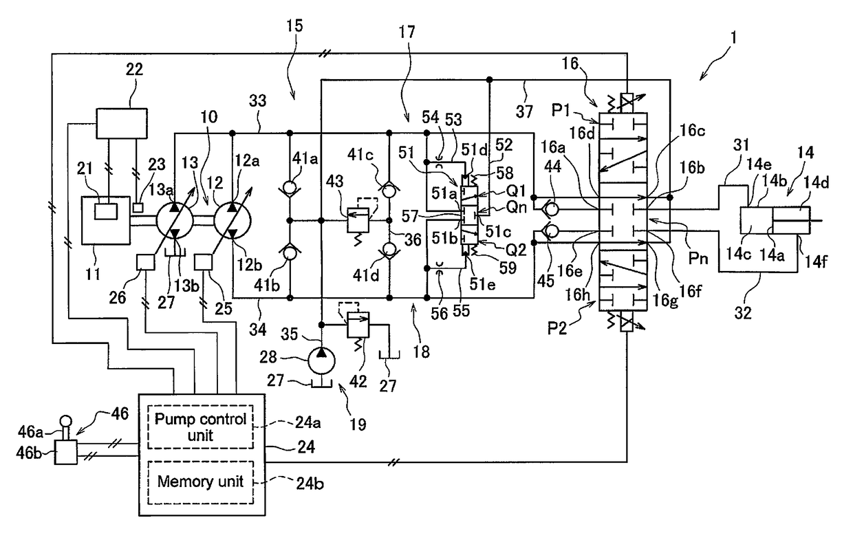
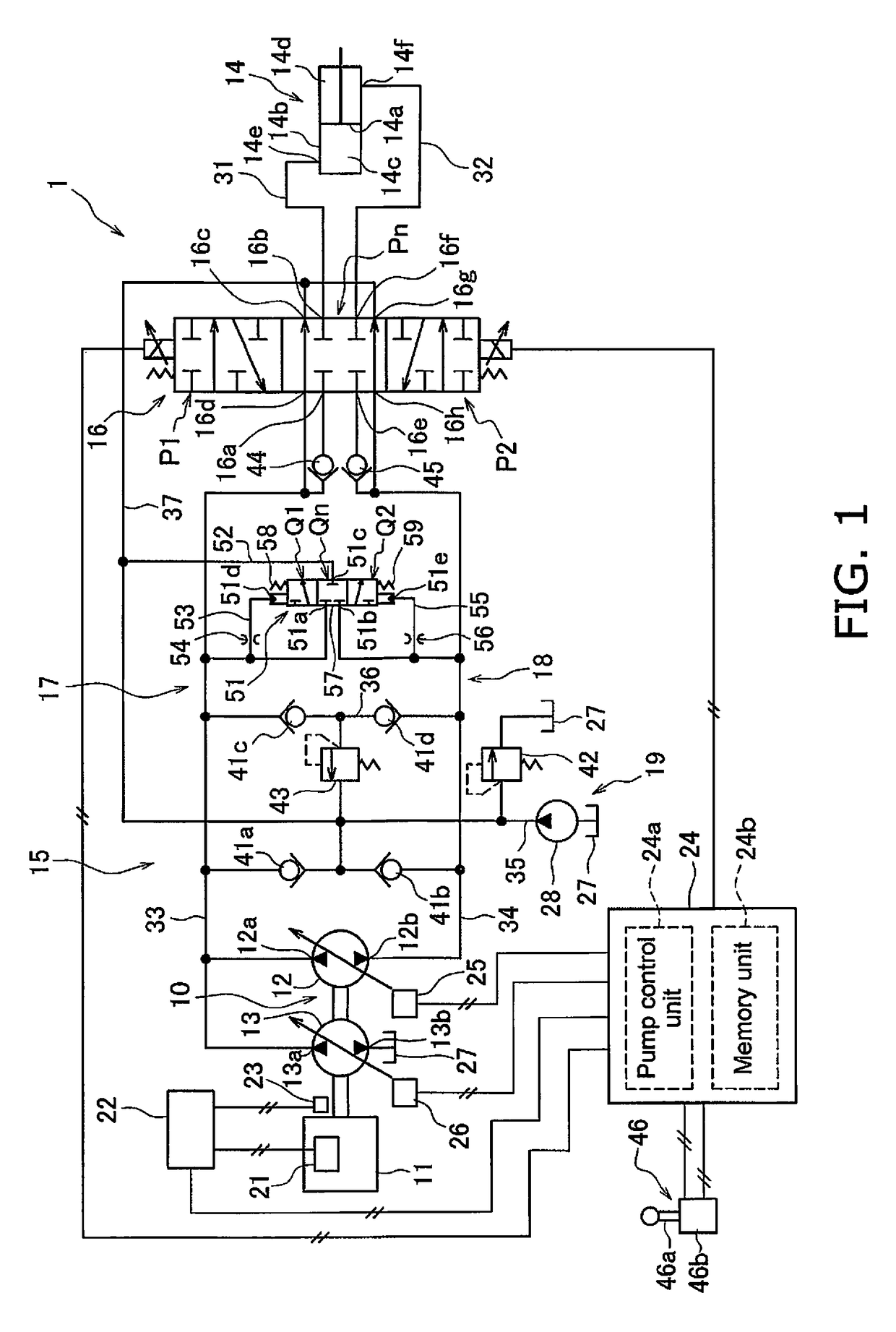
[0037]FIG. 1 is a block diagram of a configuration of a hydraulic drive system 1 according to an exemplary embodiment of the present invention. The hydraulic drive system 1 is installed on a work machine, such as a hydraulic excavator, a wheel loader, or a bulldozer. The hydraulic drive system 1 includes an engine 11, a main pump 10, a hydraulic cylinder 14, a hydraulic fluid flowpath 15, a flowpath switching valve 16, a shuttle valve 51, an engine controller 22, and a pump controller 24.

[0038]The engine 11 drives the main pump 10. The engine 11 is a diesel engine, for example, and the output of the engine 11 is controlled by adjusting an injection amount of fuel from a fuel injection pump 21. The adjustment of the fuel injection amount is performed by the engine controller 22 controlling the fuel injection device 21. An actual rotat...


PUM


Abstract

A shuttle valve connects a second flowpath and a drain flowpath when the hydraulic pressure in a first flowpath is greater than the hydraulic pressure in the second flowpath. The shuttle valve connects the first flowpath and the drain flowpath when the hydraulic pressure in a second flowpath is greater than the hydraulic pressure in the first flowpath. The ratio between the pressure receiving area of a first pressure section and the pressure receiving area of a second pressure section is the same as the ratio between the pressure receiving area of a first chamber side and the pressure receiving area of a second chamber side of a cylinder rod.

Description

CROSS-REFERENCE TO RELATED APPLICATIONS[0001]This application is a U.S. National stage application of International Application No. PCT / JP2012 / 073117, filed on Sep. 11, 2012. This U.S. National stage application claims priority under 35 U.S.C. §119(a) to Japanese Patent Application No. 2012-037233, filed in Japan on Feb. 23, 2012, the entire contents of which are hereby incorporated herein by reference.BACKGROUND[0002]Field of the Invention[0003]The present invention relates to a hydraulic drive system.[0004]Background Art[0005]Work machines, such as a hydraulic excavator or a wheel loader, are equipped with hydraulic cylinders. Hydraulic fluid discharged from a hydraulic pump is supplied to the hydraulic cylinder through a hydraulic circuit. For example, Japanese Laid-open Patent Publication No. 2002-54602 describes a work machine equipped with a hydraulic closed circuit for supplying hydraulic fluid to the hydraulic cylinders. Kinetic energy and potential energy of the members dri...

Claims


Application Information

Patent Timeline
Patent Type & Authority Patents(United States)
IPC IPC(8): F15B15/02E02F9/22F15B11/17
CPCF15B15/02E02F9/226E02F9/2217E02F9/2242E02F9/2282E02F9/2289E02F9/2292E02F9/2296F15B11/17F15B2211/20546F15B2211/20561F15B2211/20576F15B2211/30525F15B2211/327F15B2211/613F15B2211/633F15B2211/6346F15B2211/7053F15B2211/785
Inventor AKIYAMA, TERUOIIDA, NOBORUSAITO, KOJIYAMASHITA, KOJI
Owner KOMATSU LTD
Why Eureka
Try Eureka