LED lighting device having a prolonged life during high temperature operation

Inactive Publication Date: 2017-10-17
CHICONY POWER TECH CO LTD
View PDF4 Cites 55 Cited by
  • Summary
  • Abstract
  • Description
  • Claims
  • Application Information

AI Technical Summary

Benefits of technology

[0008]The present invention has been accomplished under the circumstances in view. It is therefore the main object of the present invention to provide a LED lighting device, which comprises a LED light housing and a LED light-emitting module. The LED light housing comprises a hollow outer shell, a reflector cup mounted in the hollow outer shell, and a lens mounted in the reflector cup. The hollow outer shell comprises an accommodation chamber, an opening located in a bottom side thereof in communication with the accommodation chamber and the space outside the LED light housing, and a planar mounting surface located on the center of a top side of the accommodation chamber and facing toward the opening. The reflector cup is mounted in the accommodation chamber of the hollow outer shell, comprising a lens mounting hole located on the center of a closed top side thereof and a conical reflective surface defined therein and gradually increased in diameter from the lens mounting hole toward an opposing bottom open side of the reflector cup. The lens is mounted in the lens mounting hole of the reflector cup, comprising a light exit surface facing toward the conical reflective surface of the reflector cup. The LED light-emitting module comprises a circuit board mounted between the planar mounting surface of the hollow

Problems solved by technology

However, conventional lamp bulb ort lamp tube type lighting devices have the drawbacks of quick light attenuation, high power consumption, large amount of waste heat and short lifespan.
However, conventional downlights have high brightness and can produce a high temperature during operation, causing thermal damage to commodities, counters, surrounding upholsteries.
Further, the lifespan of fluorescent lamps will be relatively reduced when working in a high temperature environment for a long time.
Making these mo

Method used


Image

  • LED lighting device having a prolonged life during high temperature operation
  • LED lighting device having a prolonged life during high temperature operation
  • LED lighting device having a prolonged life during high temperature operation

Examples


Example

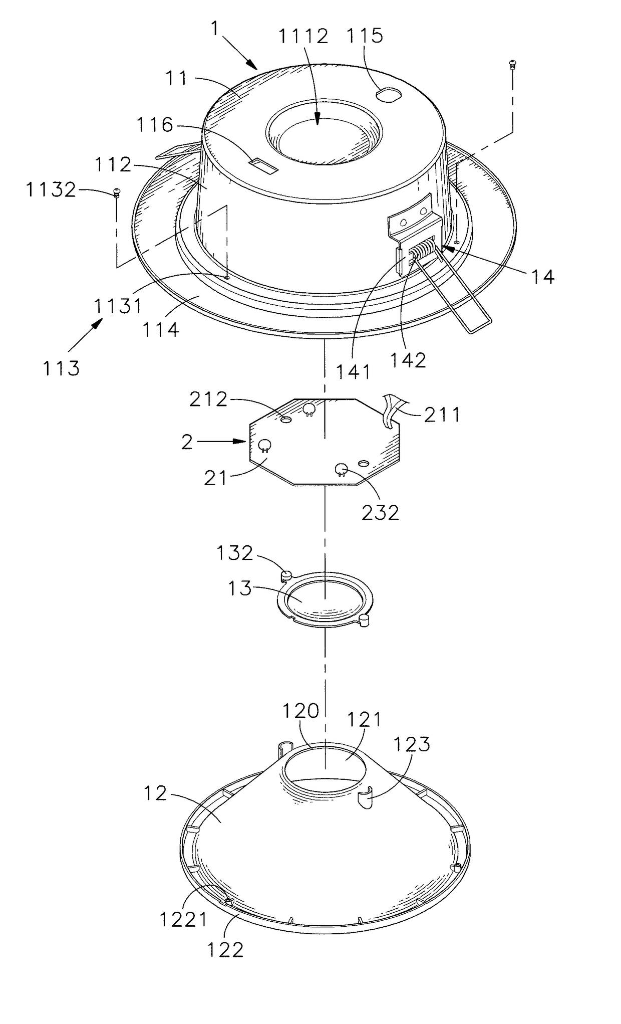
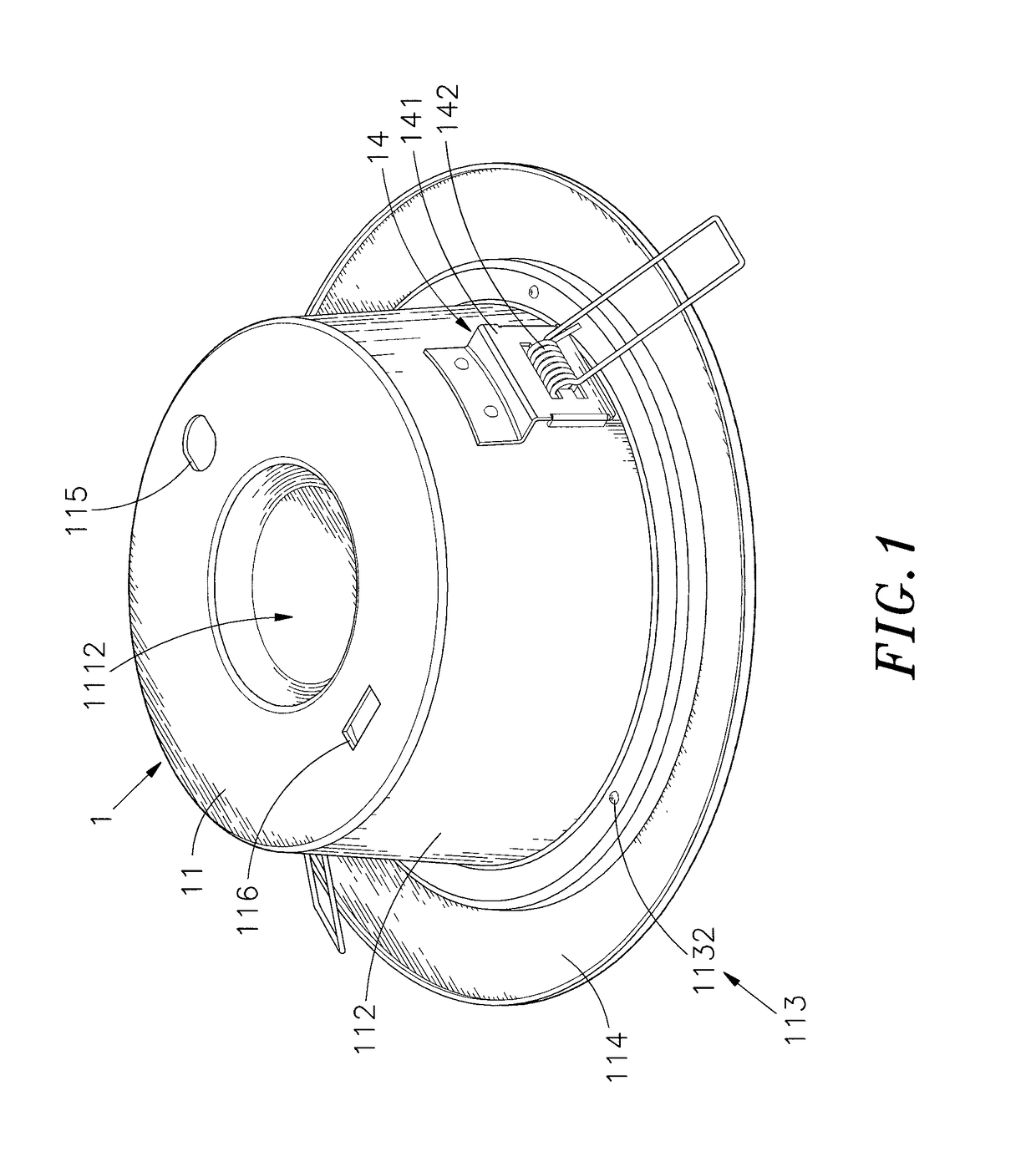
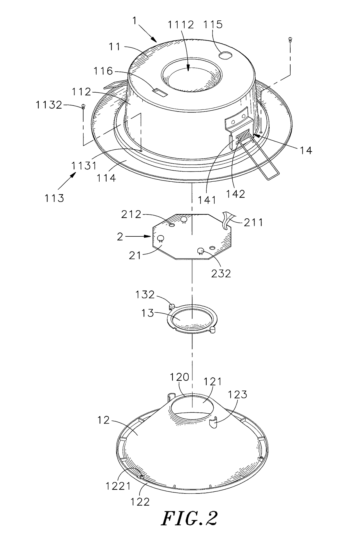
[0021]Referring to FIGS. 1-6, an oblique top elevational view of a LED lighting device in accordance with the present invention, an exploded view of the LED lighting device, another exploded view of the LED lighting device, a front sectional exploded view of the LED lighting device and a front sectional assembly view of the LED lighting device are shown. As illustrated, the LED lighting device comprises a LED light housing 1 and a LED light-emitting module 2.

[0022]The LED light housing 1 comprises a hollow outer shell 11, a reflector cup 12, a lens 13, and a plurality of mounting devices 14. The hollow outer shell 11 comprises an accommodation chamber 110, an opening 1101 located in a bottom side thereof in communication with the accommodation chamber 110 and the outside space, a planar mounting surface 111 located on the center of a top side of the accommodation chamber 110 and facing toward the opening 1101, an annular heat dissipation space 1111 defined in the accommodation chamb...


PUM


Abstract

LED lighting device includes LED light housing including hollow outer shell with planar mounting surface defined inner top side of accommodation chamber to face toward bottom opening and reflector cup mounted accommodation chamber and defining conical reflective surface therein and carrying lens at top center thereof with light exit surface of lens facing toward bottom opening of hollow outer shell, LED light-emitting module including circuit board mounted between planar mounting surface and lens, array of LEDs arranged front side of circuit board and control circuit with driver IC and capacitor thereof respectively arranged opposing front and back sides of circuit board for converting inputted AC power into stabilized DC power for driving LEDS. This structural design effectively increases available surface area of circuit board for circuit layout and related circuit layout insulation distance, allows installation of relatively larger amount of LEDs to increase overall brightness and makes reflector cup replaceable.

Description

BACKGROUND OF THE INVENTION[0001]1. Field of the Invention[0002]The present invention relates to LED lighting technology and more particularly, to a LED lighting device, which comprises a LED light housing consisting of a hollow outer shell, a reflector cup and a lens, and a LED light-emitting module having light-emitting diodes and a control circuit carried on a circuit board thereof, wherein the light-emitting diodes and a driver IC of the control circuit are arranged on a front side of the circuit board and a capacitor of the control circuit is arranged on an opposing back side of the circuit board, and thus, the surface area of the circuit board for circuit layout and the related circuit layout insulation distance are maximized.[0003]2. Description of the Related Art[0004]Lamps play a very important role in our daily life, and can provide bright illumination and clear visibility, allowing night activities to be carried out smoothly. In addition to indoor lighting, lamps can also...

Claims


Application Information

Patent Timeline
IPC IPC(8): F21V15/01F21V17/12F21V29/508F21V23/00F21K9/69F21K9/68F21K9/20F21V21/30F21Y105/10
CPCF21K9/20F21K9/68F21K9/69F21V29/508F21V15/01F21V17/12F21V23/005F21Y2105/10F21Y2115/10F21V29/83F21K9/233F21V13/04F21V23/006F21V23/009F21V29/773F21S8/026
Inventor HUANG, HUAN-HSIANGLIN, CHUCH-HSUN
Owner CHICONY POWER TECH CO LTD
Why Eureka
Try Eureka