Intervertebral disc prosthesis and intervertebral prosthetic unit

a technology of intervertebral discs and prostheses, which is applied in the field of self-adjusting and self-stabilizing intervertebral disc prosthesis and intervertebral prosthetic units, can solve the problems of high patient risk, difficult prosthesis technology, and unsatisfactory kinematics of the vertebral column

Active Publication Date: 2017-10-24
LEMAIRE VALERIE
View PDF13 Cites 0 Cited by
  • Summary
  • Abstract
  • Description
  • Claims
  • Application Information

AI Technical Summary

Benefits of technology

[0014]The disc prosthesis with two cores still has a simple design, while being compact and providing good stability. This prosthesis also makes it possible to control relative movements between the different elements constituting it, and thus makes it possible to allow natural movements of the vertebral column.
[0016]According to a second embodiment, especially preferred for the simplicity of implantation, the prosthesis advantageously comprises a single upper plate provided with first and second convex surfaces, a single lower plate provided with first and second concave surfaces, the upper and lower plates being separated in the frontal and median planes by the first and second mobile cores, the first and second convex surfaces and the first and second concave surfaces being arranged so that the first and second mobile cores are arranged on each side of and symmetrically with respect to the median plane of said prosthesis in said assembled configuration. This configuration makes it possible to reinforce the robustness of the prosthesis.
[0018]The invention also relates to an intervertebral prosthetic assembly intended to be provided in the place of an intervertebral fibrocartilage disc of the vertebral column between an upper vertebra and a lower vertebra. This intervertebral prosthesis is remarkable in that it comprises at least one lumbar disc prosthesis, in particular as described above, and a posterior articular prosthesis, the posterior articular prosthesis comprising at least two articular blades each intended to be coupled, respectively, to an upper vertebra and a lower vertebra by way of connection means, the articular blades being arranged adjacently and partially tangentially, the articular blades being equipped with guide means arranged so as to allow mobility of the articular blades one with respect to another according to a curve of which the centre C3 of the radius of curvature is provided on the same side of the posterior articular prosthesis as the implantation of the connection means. The proper positioning of the upper and lower vertebrae can thus be ensured in both latero-lateral and anteroposterior directions.
[0020]The guide element can be a ball housed in a recess provided in the articular blade, the recess having a spherical profile. The ball thus enables pivoting in the frontal plane between the articular blades, allowing a lateral tilt of the vertebral column similar to the natural tilt.
[0021]In a preferred embodiment, the connection means comprise, for each articular blade, two connection rods intended to be secured to one of the upper and lower vertebrae, the connection rods being arranged on each side of and symmetrically with respect to the median plane of the articular blade, each articular blade comprising a cuff, arranged beyond the area of tangency of the articular blades and capable of receiving one of the connection rods. This configuration enables robust anchoring of the posterior articular prosthesis, ensuring the efficacy thereof over time.
[0022]Each connection rod and each corresponding cuff advantageously has complementary polygonal cross-sections making it possible, once the connection rod has been fitted into the cuff, to prevent the connection rod from pivoting with respect to the articular blade.

Problems solved by technology

However, the implantation of a prosthesis of this type by the posterior approach requires passing by nerve endings, and therefore poses a high risk for the patient.
In addition, the production of such a prosthesis is technically difficult and results in unsatisfactory kinematics of the vertebral column.
However, the known bifurcated prostheses can produce adverse effects in patients with said prostheses: they indeed pose a risk of abnormal kinematics, in particular in frontal translation, or dislocation.
They therefore are not entirely satisfactory because they do not enable the natural kinematics of the vertebral column to be reproduced.
In addition, most of these bifurcated prostheses, for reasons of stability, excessive wear and control of relative movements of the different parts constituting these prostheses, require a posterior articular prosthesis to be put into place, which has the effect of considerably increasing the volume of the assembly thus produced.

Method used


Image

  • Intervertebral disc prosthesis and intervertebral prosthetic unit
  • Intervertebral disc prosthesis and intervertebral prosthetic unit
  • Intervertebral disc prosthesis and intervertebral prosthetic unit

Examples


Embodiment Construction

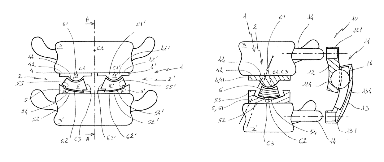
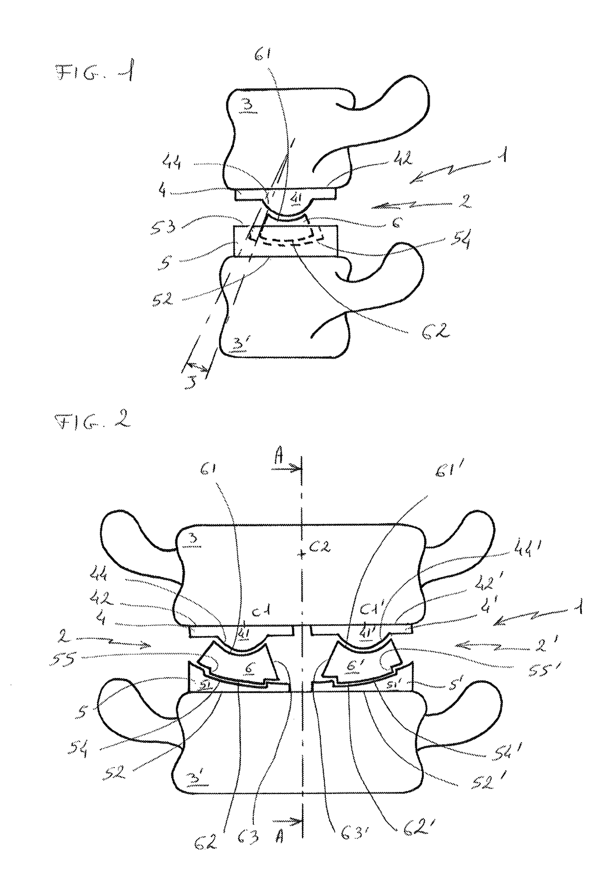
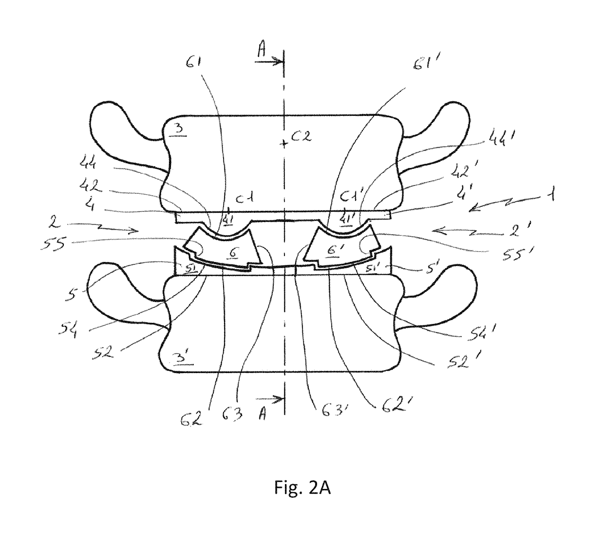
[0029]In reference to FIGS. 1 and 2, the prosthesis 1 according to the invention is intended to be arranged in the place of a fibrocartilage disc ensuring the connection between the vertebrae 3, 3′ of the vertebral column, for example the lumbar vertebrae. The prosthesis 1 comprises two subassemblies 2, 2′ arranged symmetrically with respect to the median plane of the prosthesis 1 and therefore of the vertebral column. A single subassembly 2 is visible in FIG. 1.

[0030]Each subassembly 2, 2′ comprises at least three parts, including a first plate called the upper plate 4, 4′, a second plate called the lower plate 5, 5′ and a mobile core 6, 6′ arranged between the two upper and lower plates 4, 5; 4′, 5′. The upper plate 4, 4′ and the lower plate 5, 5′ are thus articulated one with respect to the other by way of the mobile core 6, 6′.

[0031]Each upper plate 4, 4′ comprises a central body 41, 41′ of which the shape and dimensions are complementary to those of the upper vertebra 3 of the ...


PUM

PropertyMeasurementUnit
thicknessaaaaaaaaaa
radius of curvatureaaaaaaaaaa
distanceaaaaaaaaaa

Abstract

An intervertebral disc prosthesis (1) having at least one upper plateau (4, 4′) and at least one lower plateau (5, 5′), which are separated by two movable cores (6, 6′) whose lower face (62, 62′) and upper face (61, 61′) respectively match a concave surface (54, 54′) of the upper plateau (4, 4′) and a convex surface (44, 44′) of the lower plateau (5, 5′). An intervertebral prosthetic unit (10) is also described having an intervertebral disc prosthesis and a posterior articular prosthesis (11) provided with two adjacent and partially tangent articular blades (12, 13), which are each coupled to a vertebra (3, 3′) by coupling devices (14) and are connected by guide devices that allow them to move along a curve whose center C3 is provided on the same side as the implantation of said coupling means.

Description

TECHNICAL FIELD[0001]The present invention relates to a self-adjusting and self-stabilizing intervertebral disc intended to replace fibrocartilage discs providing a connection between the vertebrae of the vertebral column, in particular at the lumbar spine, as well as an intervertebral prosthesis including an intervertebral disc prosthesis associated with a posterior articular prosthesis (posterior interapophyseal articular prosthesis).PRIOR ART[0002]In the field of surgery of the lumbar portion of the vertebral column, in consideration of the risks inherent to the anterior surgical approach and the difficulty of revision surgery, most surgeons prefer the posterior approach to the lumbar spine.[0003]Thus, the use of a single prosthesis is known. However, the implantation of a prosthesis of this type by the posterior approach requires passing by nerve endings, and therefore poses a high risk for the patient. In addition, the production of such a prosthesis is technically difficult an...

Claims


Application Information

Patent Timeline
Patent Type & Authority Patents(United States)
IPC IPC(8): A61F2/44A61B17/70A61F2/30
CPCA61F2/4425A61F2/4405A61B17/7025A61F2310/00796A61F2002/304A61F2002/308A61F2002/3065A61F2002/30245A61F2002/30393A61F2002/30616A61F2002/30642A61F2002/443A61F2002/448A61F2310/00023A61F2310/00029A61F2310/00179
Inventor HANSEN, STEPHANE
Owner LEMAIRE VALERIE
Why Eureka
Try Eureka