Valve device

a valve and valve chest technology, applied in the field of valve devices, can solve the problems of insufficient reduction of pumping volume, shortened life of the diaphragm, and difficulty in improving the accuracy of the flow rate, so as to achieve the effect of suppressing the retention of fluid in the valve chest, reducing the internal volume of the valve chest, and reducing the difficulty of pumping volum

Active Publication Date: 2017-10-31
SUMITOMO RUBBER IND LTD
View PDF26 Cites 7 Cited by
  • Summary
  • Abstract
  • Description
  • Claims
  • Application Information

AI Technical Summary

Benefits of technology

[0034]In the valve device of the present invention, since the recess is formed with the inclined portion whose depth from the diaphragm gradually increases from the valve seat side toward the inflow opening, an internal volume of the valve chest increases. As a result, a proportion of a pumping volume to the internal volume of the valve chest becomes small, and most fluctuation of the internal volume of the valve chest according to the oscillation of the diaphragm is absorbed as a fluctuation of an inner pressure of the valve chest. Therefore, the pumping volume can be sufficiently reduced without making a large difference between the cross-section area of an inflow port and the cross-section area of an outflow port.
[0035]Meanwhile, if the internal volume of the valve chest is simply increased, there is concern about retention of the fluid in the valve chest. In the present invention, however, as the inclined portion is formed so that the fluid smoothly flows from the inflow opening to the valve seat, the retention of the fluid in the valve chest is suppressed. Further, as the first protrusion is provided on the both sides of the inflow opening in the width direction, the inclined portion has the taper shape such that its width gradually increases from the inflow opening toward the valve seat. Thereby, the cross-section area of the fluid passage is sufficiently secured also near the outflow opening so that the smooth flow of the fluid is not hindered, and the retention of the fluid is further suppressed.

Problems solved by technology

For this reason, it is difficult to improve accuracy of the flow rate.
However, even if such method is employed, the pumping volume can not be sufficiently decreased.
On the other hand, according to the decrease of the membrane portion, a partial expansion / contraction rate of the membrane portion is increased, therefore, a problem occurs such that the life of the diaphragm is shortened.

Method used


Image

  • Valve device
  • Valve device
  • Valve device

Examples


working examples

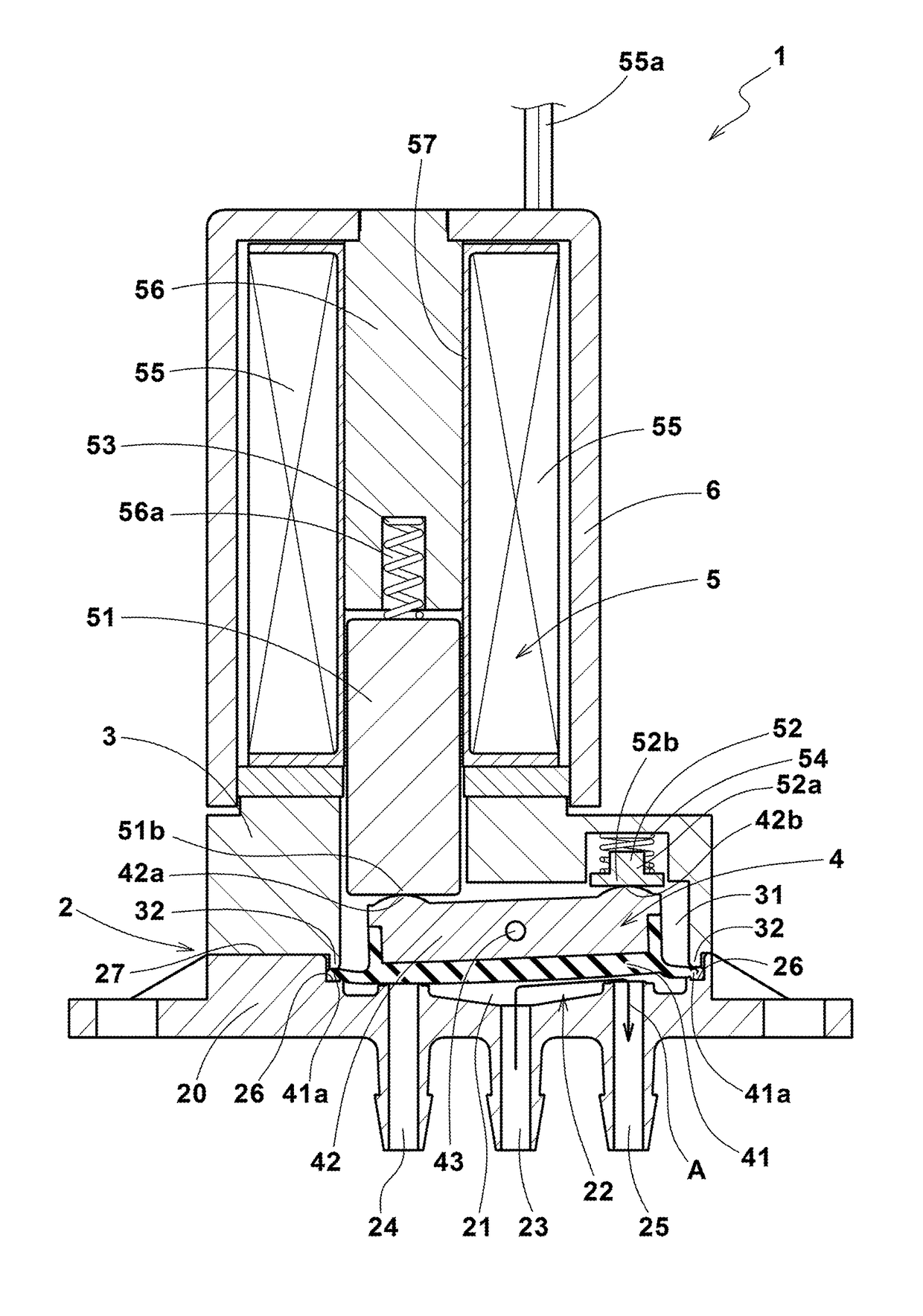
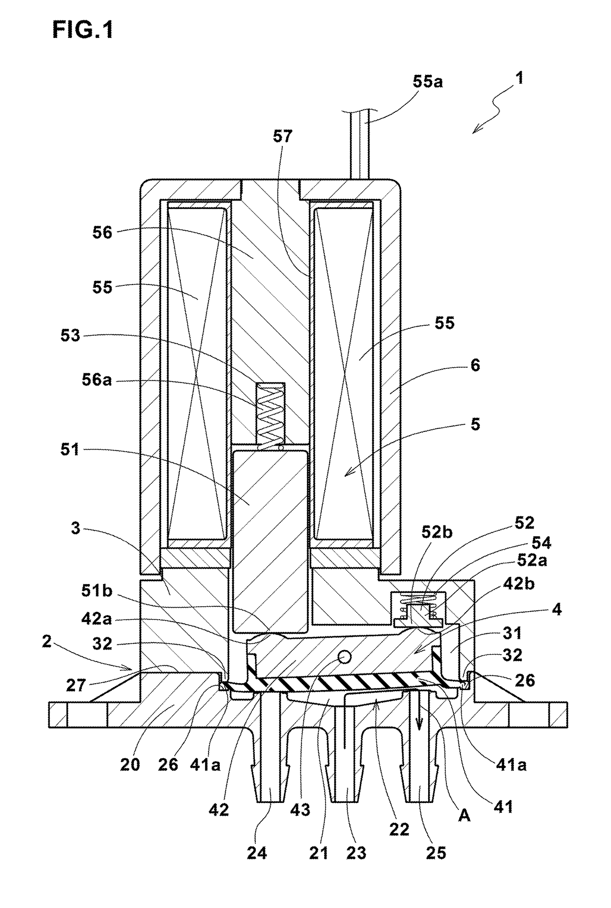
[0102]The valve device having the basic structure shown in FIG. 1 was experimentally manufactured based on specifications in Table 1, and tested for the pumping volume. As the material of the passage block PPS (polyphenylene sulfide) was used. The passage blocks having the respective specifications were experimentally produced by shaping a block made of PPS into a predetermined shape by the use of a cut processing machine. The test methods are as follows.

[0103]The passage blocks with the respective specifications were each incorporated into the valve device, and the pumping volume was measured. That is to say, all the ports were filled with water, a voltage of 12 V was applied to the solenoid coil, and a change in a water level in a tube connected to the outflow port was measured. A value that is obtained by converting the change in the water level in the tube into a volume of the tube is the pumping volume. An all-purpose projector (V12-BS produced by Nikon corporation) was used fo...


PUM


Abstract

A recess 22 provided in a passage block 20; a diaphragm covering the recess 22 to form a valve chest 21 in which a fluid flows; an inflow port 23 opened at the recess 22 and allowing the fluid to flow into the valve chest 21; an NC outflow port 24 and an NO outflow port 25 opened at the recess 22 and allowing the fluid to flow out from the valve chest 21; by oscillating the diaphragm, the diaphragm is closely fitted to any one of a first valve seat 24b formed by an opening 24a of the NC outflow port 24 and a second valve seat 25b formed by an opening 25a of the second outflow port 25, to allow the fluid in the valve chest 21 to flow out from the other outflow port. The recess 22 has a first inclined portion 81 and a second inclined portion 82 having a depth gradually increasing from the first valve seat 24b and the second valve seat 25b toward the inflow opening 23.

Description

TECHNICAL FIELD[0001]The present invention relates to a valve device to be used in various analyzing devices such as a chemical testing device, an environment analyzing device, and a biotechnology research device.BACKGROUND ART[0002]In the various analyzing devices, important problems are an improvement of measurement accuracy, an improvement of an inspecting speed, minimization of a specimen and a reagent, and downsizing of a device, and a valve device for controlling a flow rate of a fluid used in measurement is required to be further improved in its performance. Such a valve device employs a diaphragm as a valve opening / closing mechanism in order to realize excellent chemical resistance. The diaphragm forms a bulkhead that divides a valve chest, and receives an external driving force to switch fluid passages.[0003]In this kind of valve device, the housing is provided with one inflow port and two outflow ports so as to communicate with the valve chest. When the diaphragm oscillate...

Claims


Application Information

Patent Timeline
Patent Type & Authority Patents(United States)
IPC IPC(8): B01L3/00F16K11/052F16K11/02F16K7/16F16K11/04F16K7/14F16K31/06F16K27/02
CPCB01L3/567F16K7/14F16K7/16F16K11/022F16K11/04F16K11/0525F16K27/0263F16K31/0641F16K11/052B01L2400/0638B01L2200/0605F16K31/105
Inventor FUTAMATA, KAZUOISHIMARU, TAKESHIMORITA, KOUHEI
Owner SUMITOMO RUBBER IND LTD
Why Eureka
Try Eureka