Compliant touch sensor

a touch sensor and compliant technology, applied in the direction of force measurement by measuring optical property variation, programme control, force/torque/work measurement apparatus, etc., can solve the problems of difficult to sense small areas, relatively stiff bumpers, and collisions between moving objects, so as to reduce noise, mitigate noise, and block noise

Active Publication Date: 2017-10-31
VISION ROBOTICS
View PDF14 Cites 5 Cited by
  • Summary
  • Abstract
  • Description
  • Claims
  • Application Information

AI Technical Summary

Benefits of technology

[0013]Advantages of the compliant touch sensor described in this invention include: (1) very low inertia; (2) very low compressive force, especially in local areas; (3) very quick sensing of collisions; (4) significant over travel after collision is sensed, unlike resistive sensors that minimize displacement for example; (5) sensors can cover large areas; (6) sensors can be of arbitrary shapes, and may for example be placed around corners; (7) sensors may be broken into multiple sensing zones to localize the contact force; (8) no dead zones; (9) very high reliability and robustness; (10) low manufacturing cost.
[0015]The sensor may also detect movement of an object it is in contact with, including but not limited to shear movement of the object relative to the sensor. For example, when an object such as a piece of cloth, a piece of paper, or a book is pinched between the sensor and another object and the object is pulled sideways, the sensor may detect this load. The shear motion of the object relative to the sensor may for example change the orientation of the signal transmitter relative to the signal receiver (for example by creating a shear motion between them), which thereby changes the electromagnetic field between them. An embodiment with a sensor that detects shear movement and shear load may be used for example in a sewing application where it is beneficial to sense when the fabric is stretching.
[0017]In one or more embodiments the compliant layer may be configured to provide over travel after detection of a contact. For example, a contact may be detected when the separation distance between the signal transmitter and the signal receiver reaches a detection distance; increases in contact forces beyond this point may further compress the compliant layer, reducing the separation distance below the detection distance. This over travel feature of the sensor may provide protection to equipment on which the sensor is installed, or to objects that this equipment touches or holds. For example, in one or more embodiments the sensor may be installed on a mobile robot bumper. The compliant layer in the sensor may compress when the bumper contacts an obstacle such as a wall, triggering contact detection. Because the robot control system may not respond immediately to stop or reverse motion of the robot, additional movement may occur after the contact detection. The compliance in the compliant layer beyond the detection distance provides an additional buffer to allow this continued motion without damaging the robot. Another example is an embodiment with the sensor installed in a gripper of a robot arm. If the gripper closes to grab an object, the robot control system may not respond immediately to stop or reverse this closing motion when contact is detected. Compliance in the sensor beyond the contact detection distance allows the closing motion to continue without damaging the object being gripped.
[0021]Embodiments that use received signal strength to detect contact may be susceptible to electromagnetic noise that corrupts the received signal. To eliminate or reduce the effects of noise, one or more embodiments may use a transmitted signal of a known frequency, and apply a bandpass filter to the received signal to reject noise that is outside the desired frequency band. One or more embodiments may mitigate noise by adding a conductive shielding layer or layers. The shield may block noise from reaching the signal transmitter or the signal receiver, or it may attenuate this noise. One or more embodiments may include an insulating layer between the shield and the transmitter and receiver.

Problems solved by technology

Collisions between moving objects are inevitable and are sometimes desired.
Large bumpers are required for robots operating in typical home or office environments, since robots may encounter obstacles at arbitrary heights.
The large size results in a relatively stiff bumper.
Also, depending on the mechanical design it may be hard to sense small areas in order to provide feedback for where the collision occurred.
Corners are also a problem for mechanical bumpers but are critical in practice because obstacles are often struck when a moving system tries to pass closely beside an object.
Strain gages, pressure sensitive sheets, and similar systems are often very sensitive, but typically have very little compliance.
However, the low compliance of these systems makes them unsuitable for many applications.
However, these systems are not 100% reliable; therefore mobile robots that include these sensors almost always include backup mechanical sensor / bumper combinations.
These systems perform very poorly or not at all when sensing objects that are close.
This presents problems for systems that are intended to operate in tight areas, such as a robot vacuum cleaner that is intended to get as close to walls and obstacles as possible, or robot arms that are to work side-by-side with people.
Higher quality non-contact sensors are also typically expensive.
These systems can work well for stationary obstacles such as walls or doorways, but they do not provide a general-purpose collision detection solution.
There are no known contact sensing solutions that provide very high reliability, high compliance for a soft impact, fast reaction to sense contacts quickly when they occur, and coverage of a large surface area.

Method used


Image

  • Compliant touch sensor
  • Compliant touch sensor
  • Compliant touch sensor

Examples


Embodiment Construction

[0044]A compliant touch sensor will now be described. In the following exemplary description numerous specific details are set forth in order to provide a more thorough understanding of embodiments of the invention. It will be apparent, however, to an artisan of ordinary skill that the present invention may be practiced without incorporating all aspects of the specific details described herein. In other instances, specific features, quantities, or measurements well known to those of ordinary skill in the art have not been described in detail so as not to obscure the invention. Readers should note that although examples of the invention are set forth herein, the claims, and the full scope of any equivalents, are what define the metes and bounds of the invention.

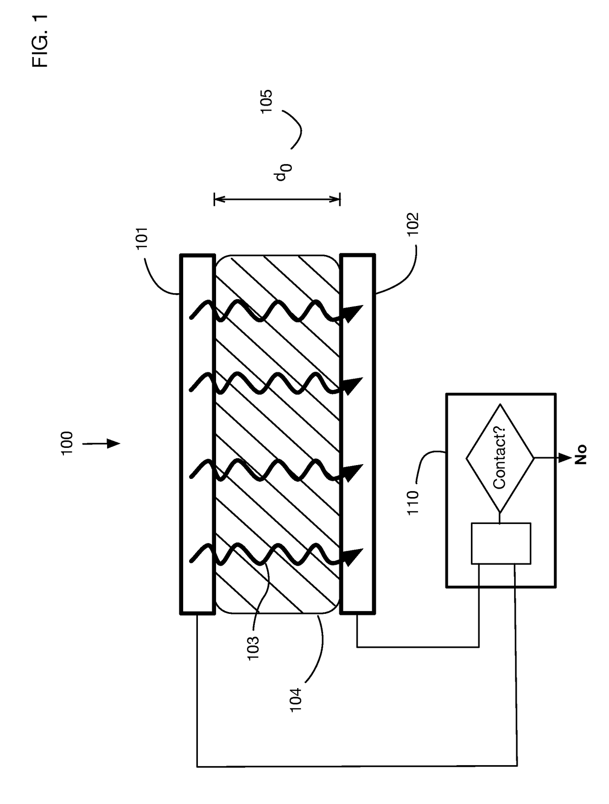
[0045]FIG. 1 illustrates an embodiment of the invention that detects contact between the sensor and an object wherein the sensor includes a compliant sensor that compresses readily with minimal force, using a transmitter and a...


PUM

PropertyMeasurementUnit
separation distanceaaaaaaaaaa
electromagnetic fieldaaaaaaaaaa
field strengthaaaaaaaaaa

Abstract

A sensor that detects contact using compression of a compliant material sandwiched between an electromagnetic signal transmitter and a corresponding signal receiver. Potential applications include inexpensive, robust collision sensors integrated into mobile robot bumpers, and sensors on robot grippers to detect grasping of an object. Deformation of the compliant material in response to contact forces changes the distance between the transmitter and the receiver, affecting the electromagnetic field between them. Changes in this electromagnetic field provide information on the location and magnitude of the contact forces. A transmitter and receiver may form opposing surfaces of a capacitor; the measured capacitance changes as the distance between transmitter and receiver changes. Alternatively, the strength of a received signal may be monitored to detect changing distance between transmitter and receiver. Shielding and signal filtering may be used to mitigate the effects of electromagnetic noise.

Description

BACKGROUND OF THE INVENTION[0001]Field of the Invention[0002]One or more embodiments of the invention are related to the field of sensors for contact detection or for collision detection, for example between a robot bumper and the environment. More particularly, but not by way of limitation, one or more embodiments of the invention enable a compliant touch sensor.[0003]Description of the Related Art[0004]Collisions between moving objects are inevitable and are sometimes desired. In most situations it is desirable to minimize damage caused by collisions. The best ways to minimize damage are to detect a collision and implement corrective action as soon as possible, and to use bumpers or other features to absorb the impact. Sensors for collision detection are of particular importance for applications such as robotics where computers control or may override human control of the motion and can react almost instantaneously upon the sensing of contact. Collision sensors may also be used in...

Claims


Application Information

Patent Timeline
Patent Type & Authority Patents(United States)
IPC IPC(8): G01L1/14B25J13/08G01L1/24G01L1/25B25J9/16
CPCB25J9/1676B25J13/085G01L1/25G01L1/24G01L1/142B25J13/082B25J13/084B25J19/0091B25J19/027B25J9/1694G05B2219/39527G01L5/0052G01L5/009
Inventor KOSELKA, HARVEYWALLACH, BRETFERENCZ, ANDREWWIGHT, RICHARD
Owner VISION ROBOTICS
Why Eureka
Try Eureka