Vibration damping device for a vehicle body

a technology of vibration damping and vehicle body, which is applied in the direction of shock absorbers, mechanical devices, transportation and packaging, etc., can solve the problems of affecting the damping force characteristic, and affecting the damping force. , to achieve the effect of stabilizing the damping force characteristic, and reducing the risk of leakag

Active Publication Date: 2017-10-31
YAMAHA MOTOR CO LTD
View PDF21 Cites 2 Cited by
  • Summary
  • Abstract
  • Description
  • Claims
  • Application Information

AI Technical Summary

Benefits of technology

[0018]The inventor of the present invention considered providing a damping force change mechanism capable of easily changing the damping force in an onboard state in the vibration damping device for a vehicle body as disclosed in Japanese Patent No. 4627389.
[0022]Preferred embodiments of the present invention provide a vibration damping device for a vehicle body that easily changes the magnitude of a damping force and stabilizes the damping force characteristic in a case in which the damping force is large.
[0027]The hydraulic oil in the first oil chamber and the second oil chamber is pressurized by the gas via the free piston. For this reason, the oil pressure in the first oil chamber and that in the second oil chamber act on the on-off valve. The on-off valve is pressed in the axial direction by a force corresponding to the difference between the pressure receiving area on the first oil chamber side and the pressure receiving area on the second oil chamber side. The pressure receiving area on the second oil chamber side is smaller than the pressure receiving area on the first oil chamber side by an area corresponding to the shaft portion fitted in the through hole of the on-off valve. That is, the on-off valve is pressed from one end side of the piston rod to the other end side together with the operation rod whose other end is opened to the atmosphere. When the on-off valve is pressed by the oil pressure, and the expanded diameter portion tightly contacts the end surface of the piston rod, the hydraulic oil is prevented from leaking through the portion between the on-off valve and the through hole. Hence, the damping force characteristic stabilizes in a state in which the on-off valve closes, and a large damping force is generated.
[0028]Hence, according to preferred embodiments of the present invention, it is possible to provide a vibration damping device for a vehicle body capable that easily changes the magnitude of a damping force and stabilizes the damping force characteristic in a case in which the damping force is large.

Problems solved by technology

However, when the damping force change mechanism described in Japanese Patent Laid-Open No. 10-331898 is applied to the vibration damping device for a vehicle body described in Japanese Patent No. 4627389, the following problem arises in a case in which the needle valve is set in a totally closed state to obtain a large damping force.
If the seal pressure is low, the hydraulic oil may leak from the gap between a through hole and the needle valve even if the needle valve is totally closed.
In particular, when the hydraulic oil is pressurized by a high pressure gas, the needle valve is always biased in the opening direction, and the risk of leakage is higher.
Even slight leakage of the hydraulic oil results in a change in the damping force characteristic.

Method used


Image

  • Vibration damping device for a vehicle body
  • Vibration damping device for a vehicle body
  • Vibration damping device for a vehicle body

Examples


first preferred embodiment

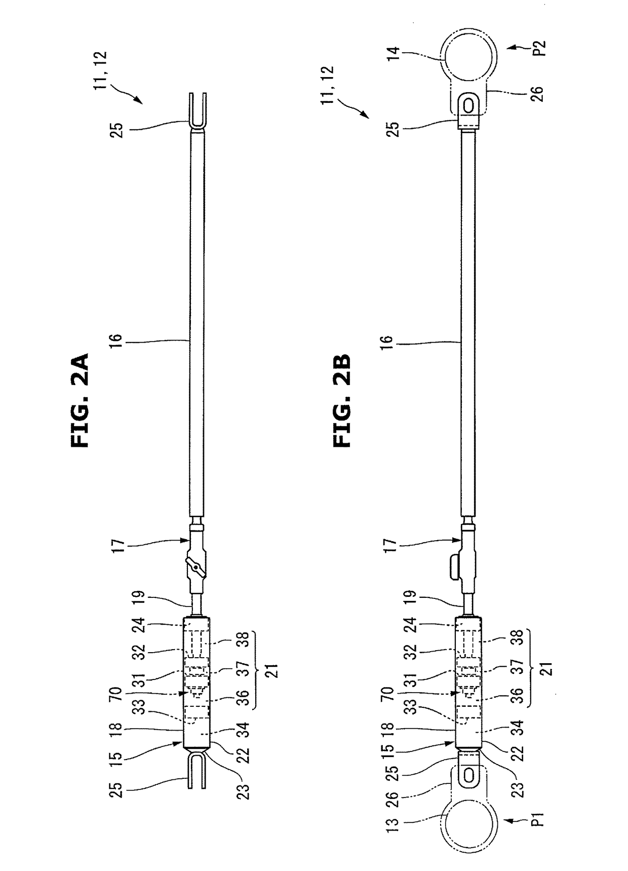
[0054]A vibration damping device for a vehicle body according to a preferred embodiment of the present invention will now be described in detail with reference to FIGS. 1 to 10.

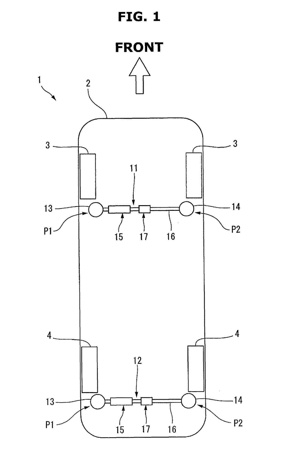
[0055]A vehicle 1 shown in FIG. 1 is, for example, a passenger car that an occupant (not shown) drives to travel. A vehicle body 2 of the vehicle 1 is provided with a left-and-right pair of front wheels 3 and a left-and-right pair of rear wheels 4.

[0056]The vehicle body 2 of this type includes a frameless body made of, for example, high-tensile steel. The vehicle body 2 elastically deforms according to an external force applied at the time of traveling and vibrates in, for example, the side-to-side and back-and-forth directions. Examples of the external force that generates vibrations are a force applied to the vehicle body 2 when the front wheels 3 and the rear wheels 4 run on uneven spots and a force received from vibrations from an engine (not shown).

[0057]To damp the unwanted vibrations of the vehicle bod...

second preferred embodiment

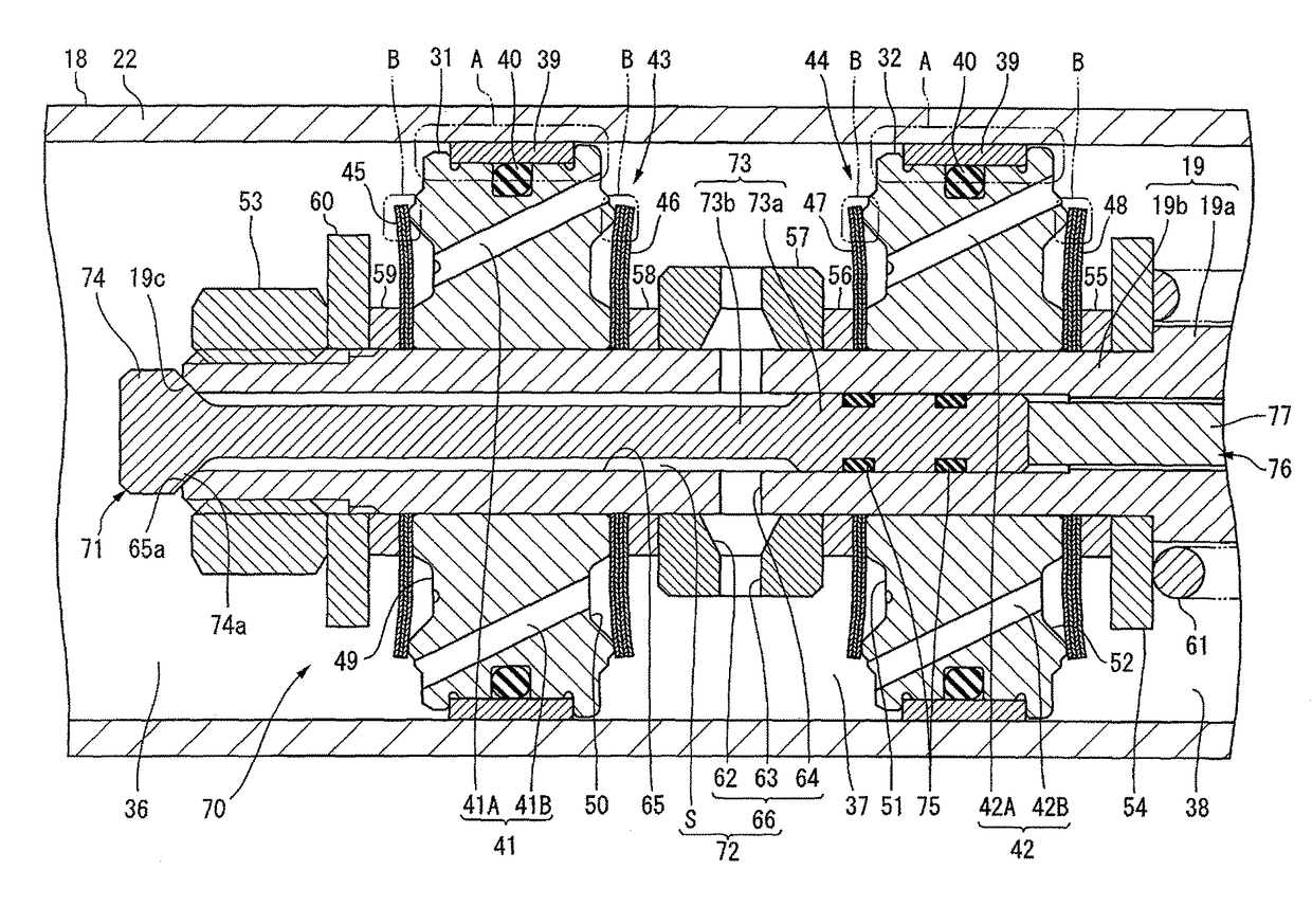
[0165]An on-off valve and an operation mechanism may be constructed as shown in FIGS. 12 to 18. The same reference numerals as described with reference to FIGS. 1 to 11 denote the same or similar members in FIGS. 12 to 18, and a detailed description thereof will appropriately be omitted. A vibration damping device for a vehicle body according to the present preferred embodiment is different from the vibration damping device for a vehicle body described in the first preferred embodiment only in the on-off valve and the operation mechanism.

[0166]An on-off valve 111 shown in FIG. 12 is of a rotation type that pivots with respect to an axis C of a piston rod 19 as the center. The on-off valve 111 includes a shaft portion 112 inserted into a through hole 65 of the piston rod 19, and an expanded diameter portion 113 provided at one end of the shaft portion 112.

[0167]The shaft portion 112 includes a columnar portion 112a having a columnar shape and is located on the axis of a second piston...

third preferred embodiment

[0196]An operation mechanism used to operate an on-off valve may be constructed as shown in FIG. 22. The same reference numerals as described with reference to FIGS. 1 to 21 denote the same or similar members in FIG. 22, and a detailed description thereof will appropriately be omitted.

[0197]A vibration damping device for a vehicle body according to the present preferred embodiment is different from the vibration damping device for a vehicle body described in the first preferred embodiment only in the operation mechanism.

[0198]An operation element 141 of an operation mechanism 76 shown in FIG. 22 is a pivot-type handle as shown in FIGS. 8 and 9 or a pivot-type lever as shown in FIG. 19. One end of an operation wire 142 is connected to the operation element 141. The other end of the operation wire 142 is connected to an input member 143 spaced apart from a first mounting position P1 or a second mounting position P2 of the vehicle body. Although not illustrated, the input member 143 ma...


PUM


Abstract

A damping force change mechanism includes an on-off valve located in a through hole of a piston rod. The on-off valve opens / closes a third hydraulic oil passage that allows a first oil chamber on a free piston side and a second oil chamber between a first piston and a second piston to communicate with each other. The on-off valve includes an expanded diameter portion in the first oil chamber extending outward in the radial direction. The expanded diameter portion faces the entire opening edge of the through hole and tightly contacts an end surface of the piston rod. The magnitude of a damping force is easily changed, and a damping force characteristic in a case in which the damping force is large is stabilized.

Description

BACKGROUND OF THE INVENTION[0001]1. Field of the Invention[0002]The present invention relates to a vibration damping device for a vehicle body that damps vibrations of a vehicle body and improves the riding comfort of the vehicle.[0003]2. Description of the Related Art[0004]The body of a vehicle is known to be slightly elastically deformed by an external force applied at the time of traveling and, because of the elastic deformation, generate a vibration having a small amplitude. The amplitude of the vibration is several ten μm to about 1 to 2 mm. The external force that causes the elastic deformation is applied from the engine or the wheels running on an uneven road surface to the vehicle body.[0005]Conventionally, to damp a vehicle body vibration of this type, a vibration damping device is mounted in a vehicle body in some cases. As a conventional vibration damping device for a vehicle body, for example, Japanese Patent No. 4627389 discloses a hydraulic device.[0006]The hydraulic v...

Claims


Application Information

Patent Timeline
Patent Type & Authority Patents(United States)
IPC IPC(8): B60G21/073F16F9/06F16F9/19F16F9/44
CPCB60G21/073F16F9/061F16F9/44F16F9/446F16F9/19B60G2206/01
Inventor YAMAZAKI, YUTAKAHARADA, TOYOJI
Owner YAMAHA MOTOR CO LTD
Why Eureka
Try Eureka