Variable speed drive for internal combustion engine

a transmission mechanism and variable speed technology, applied in the direction of gearing control, gearing elements, gearing, etc., can solve the problems of difficult to keep the temperature of the rotational angle sensor lower than an upper temperature limit, the inputting mechanism is high, and the inputting mechanism is enlarged and so on. achieve the effect of high accuracy, suppressing the impact of the inputting mechanism, and increasing the twist between the inputting mechanism and the master arm

Active Publication Date: 2017-10-31
HONDA MOTOR CO LTD
View PDF10 Cites 1 Cited by
  • Summary
  • Abstract
  • Description
  • Claims
  • Application Information

AI Technical Summary

Benefits of technology

[0017]According to an embodiment of the present invention, the master arm is disposed so as to be positioned between the input side end portion and the output side end portion of the shift spindle in the axial direction of the shift spindle. Further, the master arm and the output side end portion of the shift spindle are connected to each other by the extension collar member with the gap left from the outer circumferential face of the shift spindle. Therefore, the substantial axial length between the inputting mechanism and the master arm is increased within the axial length of the shift spindle, and the twist between the inputting mechanism and the master arm can be increased. Further, an impact from the master arm is absorbed by torsional deformation of the extension collar member and the shift spindle. Thus, the impact to be transmitted to the inputting mechanism can be suppressed. Even where the inputting mechanism and the operation mechanism are disposed on the same side on the outer side of the transmission case, the impact to be transmitted to the inputting mechanism is absorbed. Thus, a shifting operation of high accuracy can be carried out at a high speed.
[0018]According to an embodiment of the present invention, since the spring guide collar is interposed between the shift spindle and the coiled portion of the return spring, the diameter of the shift spindle can be reduced without changing the size of the return spring. Further, displacement of the shift spindle in a diametrical direction can be prevented.
[0019]Further, the biasing force of the return spring can be kept fixed without the necessity to reduce the return spring in size in conformity with reduction of the diameter of the shift spindle. Further, as the diameter of the shift spindle decreases, the torsional rigidity of the shift spindle drops. Therefore, it is possible to make the shift spindle likely to be twisted. Consequently, it is possible to absorb an impact to be transmitted to the inputting mechanism. Thus, a shift operation of high accuracy can be carried out at a high speed.
[0020]According to an embodiment of the present invention, since the washer is interposed between the extension collar member and the transmission side supporting portion, abrasion or displacement in rotational movement of the extension collar member. Thus, the transmission side supporting portion can be suppressed from being caused by rubbing between them. Especially, when the shift spindle rotates, thrust force in an axial direction from the return spring acts between the rear end face of the extension collar member and the transmission side supporting portion, and also friction increases. However, since the washer is interposed at the location, the rotation of the extension collar member or the shift spindle can be smoothened. Thus, a shift operation of higher accuracy can be carried out.
[0021]According to an embodiment of the present invention, spring steel is used for the shift spindle to increase the amount of twist of the shift spindle. Therefore, an impact to be transmitted to the inputting mechanism is absorbed. Thus, a shift operation of high accuracy can be carried out at a high speed.
[0022]According to an embodiment of the present invention, since the shift spindle is formed in a hollow cylindrical shape, the torsional rigidity of the shift spindle can be reduced. Further, the sensor shaft is inserted in the inside of the shift spindle in a spaced relationship from the inner circumferential face of the shift spindle with a gap left therebetween. Further, the one end portion of the sensor shaft is connected to the inner circumferential face of the output side end portion of the shift spindle. Furthermore, the rotational angle sensor is provided at the other end portion of the sensor shaft so as to detect the angle of rotation of the sensor shaft. Therefore, the angle of rotation of the end portion of the sensor shaft which rotates integrally with the output side end portion of the shift spindle and has the same angle of rotation as that of the output side end portion of the shift spindle can be detected by the rotational angle sensor. Thus, the impact from the master arm to be transmitted to the inputting mechanism can be suppressed, and the detection accuracy of the rotational angle sensor can be made precise. Thus, even in a case in which the inputting mechanism and the operation mechanism are disposed on the same side on the outer side of the transmission case, a shift operation of high accuracy can be carried out at a high speed.

Problems solved by technology

However, if the pivoting speed of the master arm is high, then the impact when the master arm is abutted with the stopper member is high, and this high impact is transmitted to the inputting mechanism through the shift spindle.
In order to raise the strength of the inputting mechanism to avoid the influence, it is necessary to increase the thickness or the diameter of gears, which gives rise to a problem in upsizing and so forth of the inputting mechanism.
Therefore, it may be difficult to keep the temperature of the rotational angle sensor lower than an upper temperature limit.
However, where the rotational angle sensor is attached to the inputting mechanism side, if the shift spindle has a twist angle, then the accuracy of the rotational angle sensor may degrade (the value of the sensor which detects the rotational angle of the shift spindle on the inputting mechanism side may be displaced from the actual rotational angle of the shift spindle on the operation mechanism side).
Thus, there is a problem that it is difficult to carry out a shifting operation at a high speed and with a high degree of accuracy.

Method used


Image

  • Variable speed drive for internal combustion engine
  • Variable speed drive for internal combustion engine
  • Variable speed drive for internal combustion engine

Examples


Embodiment Construction

[0034]In the following, an embodiment of the present invention is described with reference to FIGS. 1 to 8.

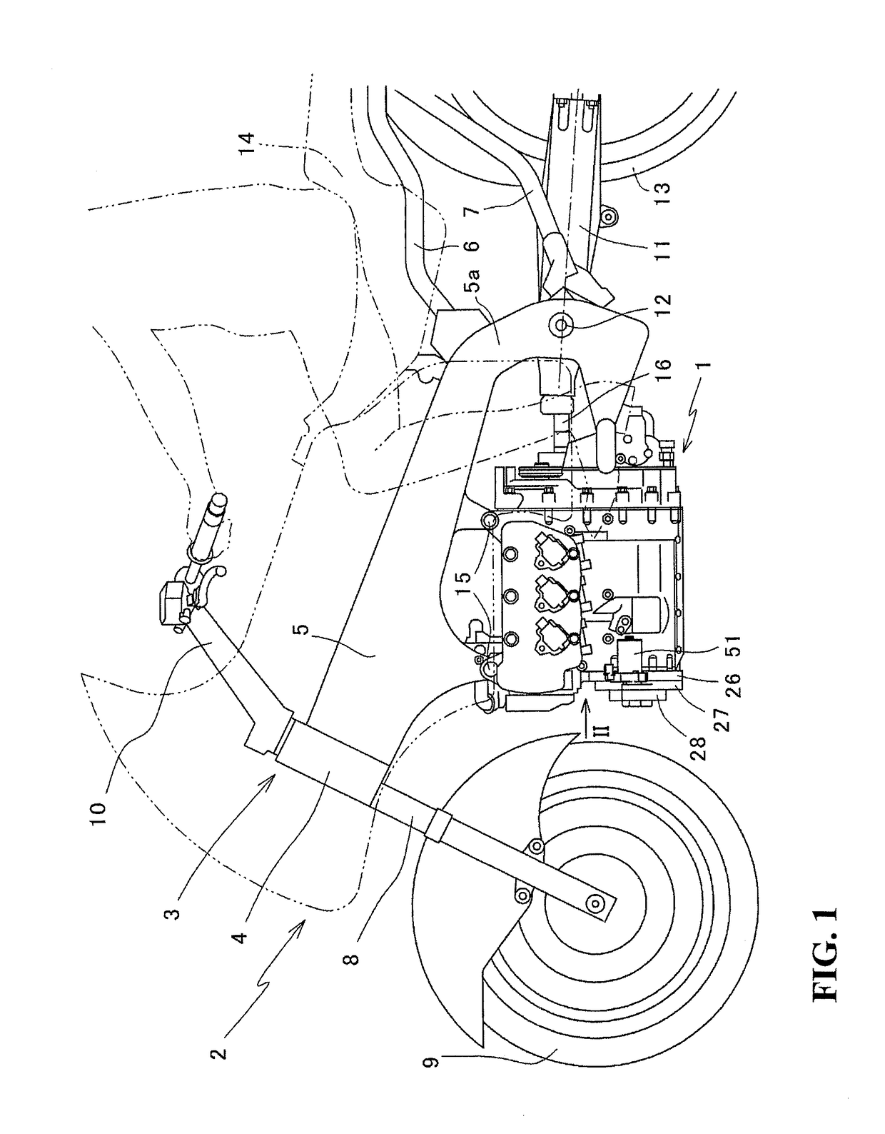
[0035]An internal combustion engine 1, including a variable speed drive 20 according to the present embodiment, is a horizontally opposed six-cylinder water-cooled four-stroke internal combustion engine in which a crankshaft 24 extends in a forward and rearward direction of the vehicle, namely, is placed longitudinally on the vehicle, on a motorcycle 2.

[0036]The directions forward, rearward, leftward and rightward are defined with reference to the usual standards wherein the straightforwardly advancing direction of the vehicle is the forward direction.

[0037]FIG. 1 is a left side elevational view of the motorcycle 2 in which the variable speed drive 20 of the internal combustion engine 1 according to the present invention is incorporated. Referring to FIG. 1, intake and exhaust systems, a fuel system and so forth are not depicted.

[0038]As depicted in FIG. 1, a vehicle body frame...


PUM


Abstract

A variable speed drive wherein an impact to be transmitted to an inputting mechanism is absorbed. A shift spindle has an input side end portion to which an inputting mechanism is connected and an output side end portion supported for rotation at a transmission side supporting portion provided on a transmission case. A master arm is positioned between the input side end portion and the output side end portion in an axial direction of the shift spindle. An extension collar member is fixed integrally to the master arm. The extension collar member connects the master arm and a connection portion provided at a location of the shift spindle rather near to the input side end portion than the output side end portion. The extension collar member extends from the connection portion toward the master arm with a gap left from an outer circumferential face of the shift spindle.

Description

CROSS-REFERENCE TO RELATED APPLICATIONS[0001]The present application claims priority under 35 USC 119 to Japanese Patent Application No. 2014-071772 filed Mar. 31, 2014 the entire contents of which are hereby incorporated by reference.BACKGROUND OF THE INVENTION[0002]1. Field of the Invention[0003]The present invention relates to a variable speed drive for driving a transmission mechanism of an internal combustion engine.[0004]2. Description of Background Art[0005]Conventionally, a variable speed drive for driving a transmission mechanism of an internal combustion engine includes a shift motor for rotating a shift spindle for the automatic transmission. See, for example, Japanese Patent Laid-Open No. 2011-208766.[0006]In the structure disclosed in Japanese Patent Laid-Open No. 2011-208766 (hereinafter referred to as prior art), an inputting mechanism and shift position changing driving means, which is an operation mechanism, are disposed in such a manner that they are distributed to...

Claims


Application Information

Patent Timeline
Patent Type & Authority Patents(United States)
IPC IPC(8): F16H61/28F16H61/32F16H63/18F16H3/00F16H3/089F16H3/16
CPCF16H61/28F16H61/32F16H63/18Y10T74/19251F16H3/089F16H3/16F16H3/006
Inventor MIZUNO, KINYAFUJIMOTO, YASUSHIMAKITA, HIROYUKI
Owner HONDA MOTOR CO LTD
Why Eureka
Try Eureka