Heat exchanger and air conditioning system having an allocation tube within heat exchanger manifold

a heat exchanger and air conditioner technology, applied in the field of air conditioning technology, can solve the problems of inability to uniformly distribute refrigerant, low and high cost of above two solutions, and achieve the effect of contributing to the efficiency of heat exchanger

Active Publication Date: 2017-11-07
ZHEJIANG SANHUA INTELLIGENT CONTROLS CO LTD
View PDF6 Cites 0 Cited by
  • Summary
  • Abstract
  • Description
  • Claims
  • Application Information

AI Technical Summary

Benefits of technology

[0007]In view of the above, the heat exchanger connects to the two connecting pipes via one manifold, wherein one connecting pipe connects to the manifold via the allocation tube, and the other connecting pipe connects to the manifold via the opening provided on the tube wall of the manifold. The two connecting pipes are prevented from being interfered by each other, such that appropriate diameters may be respectively configured for the two connecting pipes. In this way, the refrigerant in different states may be uniformly distributed when the heat exchanger operates under different modes, which contributes to the efficiency of the heat exchanger.
[0010]In view of the above, the heat exchanger connects to the two connecting pipes via one manifold, wherein one connecting pipe connects to the manifold via the allocation tube, and the other connecting pipe connects to the manifold via the opening provided on the tube wall of the manifold. The two connecting pipes are prevented from being interfered by each other, such that appropriate diameters may be respectively configured for the two connecting pipes. In this way, the refrigerant in different states may be uniformly distributed when the heat exchanger operates under different modes, which contributes to the efficiency of the heat exchanger.

Problems solved by technology

However, batteries are key components for supplying power of the electric automobiles, and cost and the capacity / weight have somehow restricted the development of the new energy vehicles.
However, the cost of the above two solutions are relatively high.
On the other hand, when the heat exchanger adopts micro-channels, the refrigerant may not be uniformly distributed.

Method used


Image

  • Heat exchanger and air conditioning system having an allocation tube within heat exchanger manifold
  • Heat exchanger and air conditioning system having an allocation tube within heat exchanger manifold
  • Heat exchanger and air conditioning system having an allocation tube within heat exchanger manifold

Examples


Embodiment Construction

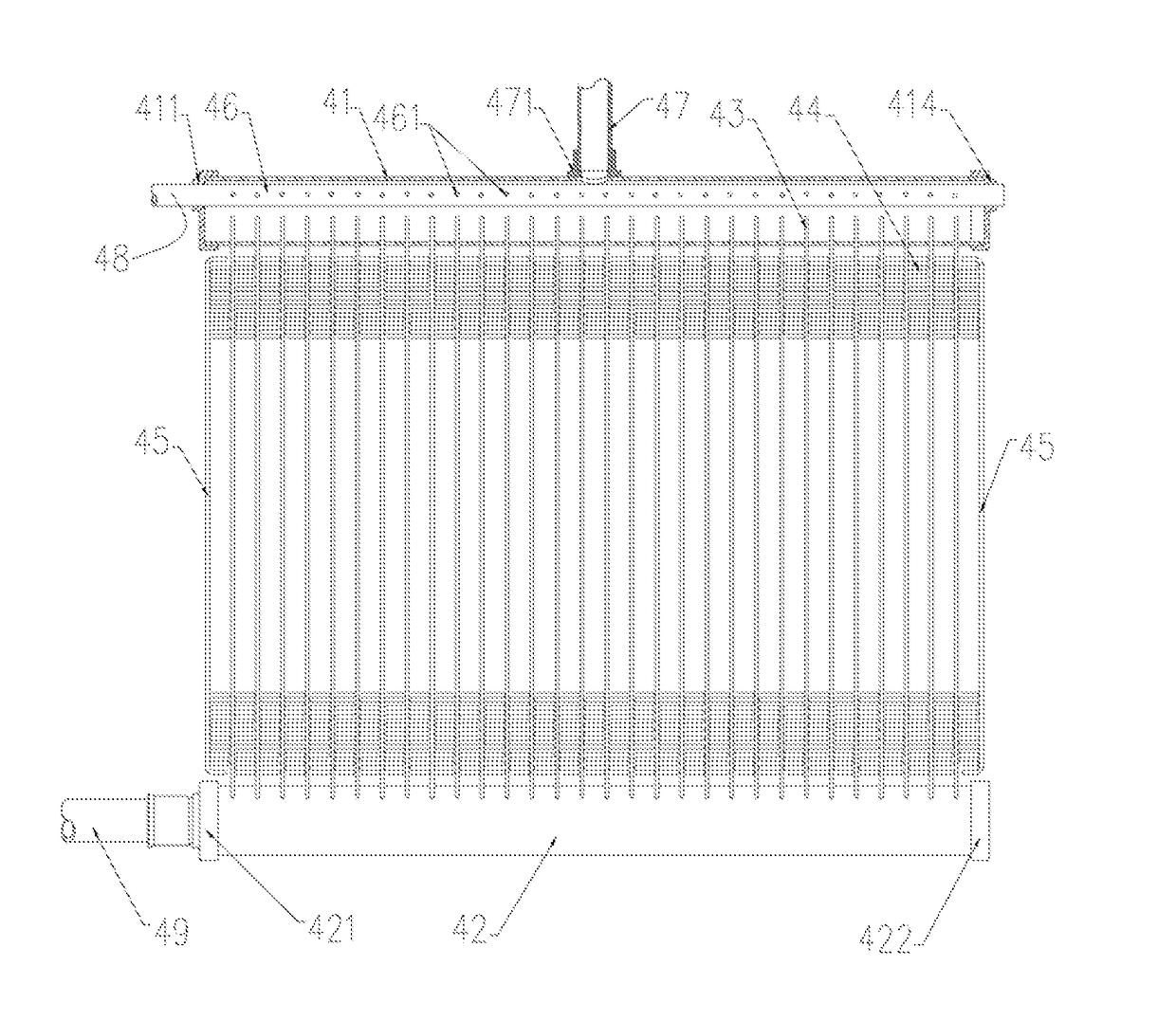
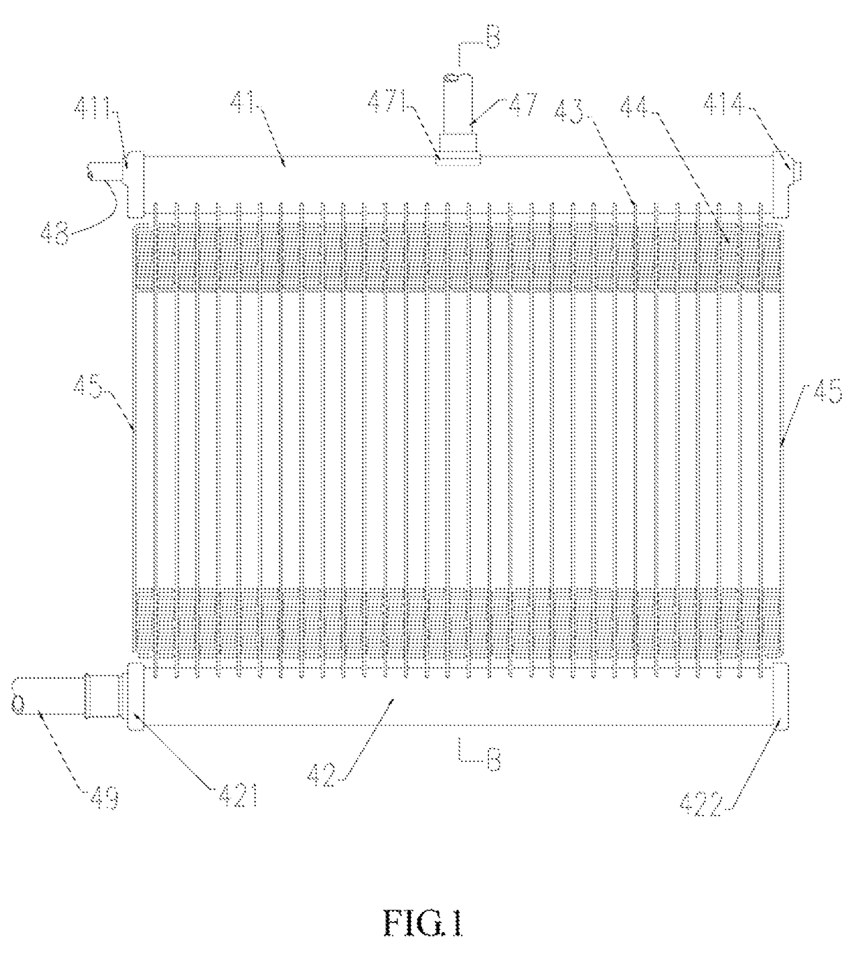
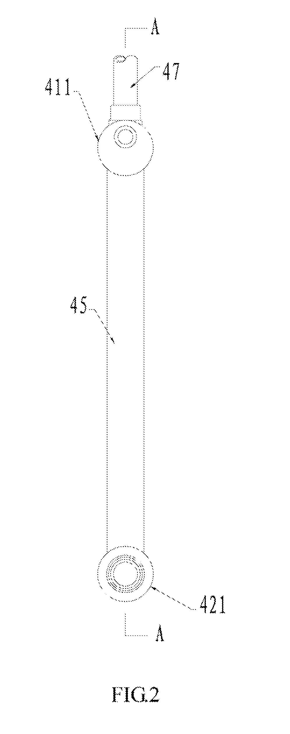
[0023]The present disclosure relates to a heat exchanger and an air-condition system including the heat exchanger. One end of the heat exchanger includes two connecting pipes, and the other end of the heat exchanger includes one connecting pipe. The two connecting pipes at the same end correspond to refrigerant in different states. The diameters of the two connecting pipes are different such that the refrigerant in different states may be uniformly allocated, which contributes to the efficiency of the heat exchanger.

[0024]Embodiments of the invention will now be described more fully hereinafter with reference to the accompanying drawings, in which embodiments of the invention are shown.

[0025]FIGS. 1-10 illustrate the heat exchanger in accordance with one embodiment. As shown, the heat exchanger includes a first manifold 41, a second manifold 42, a plurality of flat tubes 43 between the first manifold 41 and the second manifold 42, and a plurality of fins 44 arranged between each two...


PUM


Abstract

A heat exchanger includes a first manifold, a second manifold, a plurality of flat tubes, and a plurality of fins. Two ends of the first manifold are respectively sealed with a cap. The heat exchanger further includes a first connecting pipe, a second connecting pipe, and a third connecting pipe. The first connecting pipe communicates with the first manifold via a second opening, the second connecting pipe communicates with an allocation tube, and the third connecting pipe communicates with the second manifold. A diameter of the first connecting pipe is greater than the diameter of the allocation tube. The two connecting pipes of the heat exchanger correspond to refrigerant in different states. The diameters of the two connecting pipes are different such that the refrigerant in different states may be uniformly allocated, which contributes to the efficiency of the heat exchanger.

Description

BACKGROUND OF THE INVENTION[0001]1. Field of the Invention[0002]The present disclosure relates to air-condition technology, and more particularly to a heat exchanger and an air-condition system having the heat exchanger.[0003]2. Discussion of the Related Art[0004]With the development of low-carbon economy, strict demands regarding energy saving and emission reduction have been proposed. New energy vehicles have been newly developed in car industry. Electric automobiles or hybrid automobiles are characterized by energy conservation, and thus have been the current trend. However, batteries are key components for supplying power of the electric automobiles, and cost and the capacity / weight have somehow restricted the development of the new energy vehicles. It can be understood that the new energy vehicles also require newly design air-condition system for reducing the consumed energy, which may be, for instance, heat pump air-condition system.[0005]With respect to the heat pump air-con...

Claims


Application Information

Patent Timeline
Patent Type & Authority Patents(United States)
IPC IPC(8): F25B41/04F25B6/04F25B5/04F28D21/00F25B1/00F25B39/02F28F9/02F25B39/04
CPCF25B41/046F28F9/0273F25B6/04F28F2250/06F25B1/00F25B5/04F25B39/028F25B39/04F25B2341/0662F25B2400/0409F25B2400/0411F28D2021/0084F28D2021/0085F28F9/0231F28F9/0246F28F9/0275F28F2250/00F25B41/39
Inventor YE, KE-LI
Owner ZHEJIANG SANHUA INTELLIGENT CONTROLS CO LTD
Why Eureka
Try Eureka