
Overhang enclosure of a panoramic optical device to eliminate double reflection

a technology of optical device and overhang enclosure, which is applied in the field of improving the overhang enclosure of the panoramic optical device to eliminate double reflection, can solve the problems of difficult to provide high-quality optics in the panoramic camera, limited software correction distortion correction, and inability to easily correct the distortion caused by too much light reaching the image sensor

Inactive Publication Date: 2017-11-07
HOYOS INTEGRITY CORP
View PDF20 Cites 21 Cited by
  • Summary
  • Abstract
  • Description
  • Claims
  • Application Information

AI Technical Summary

Benefits of technology

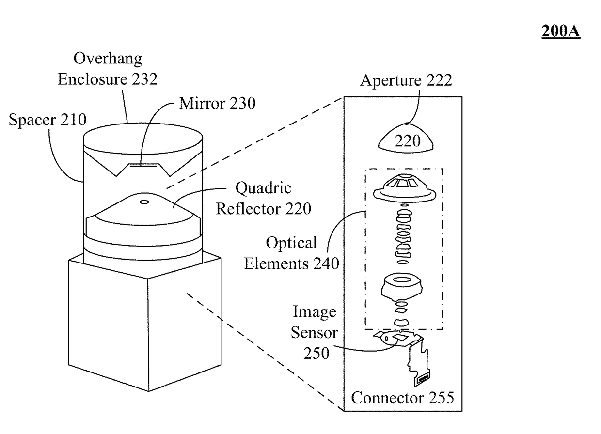
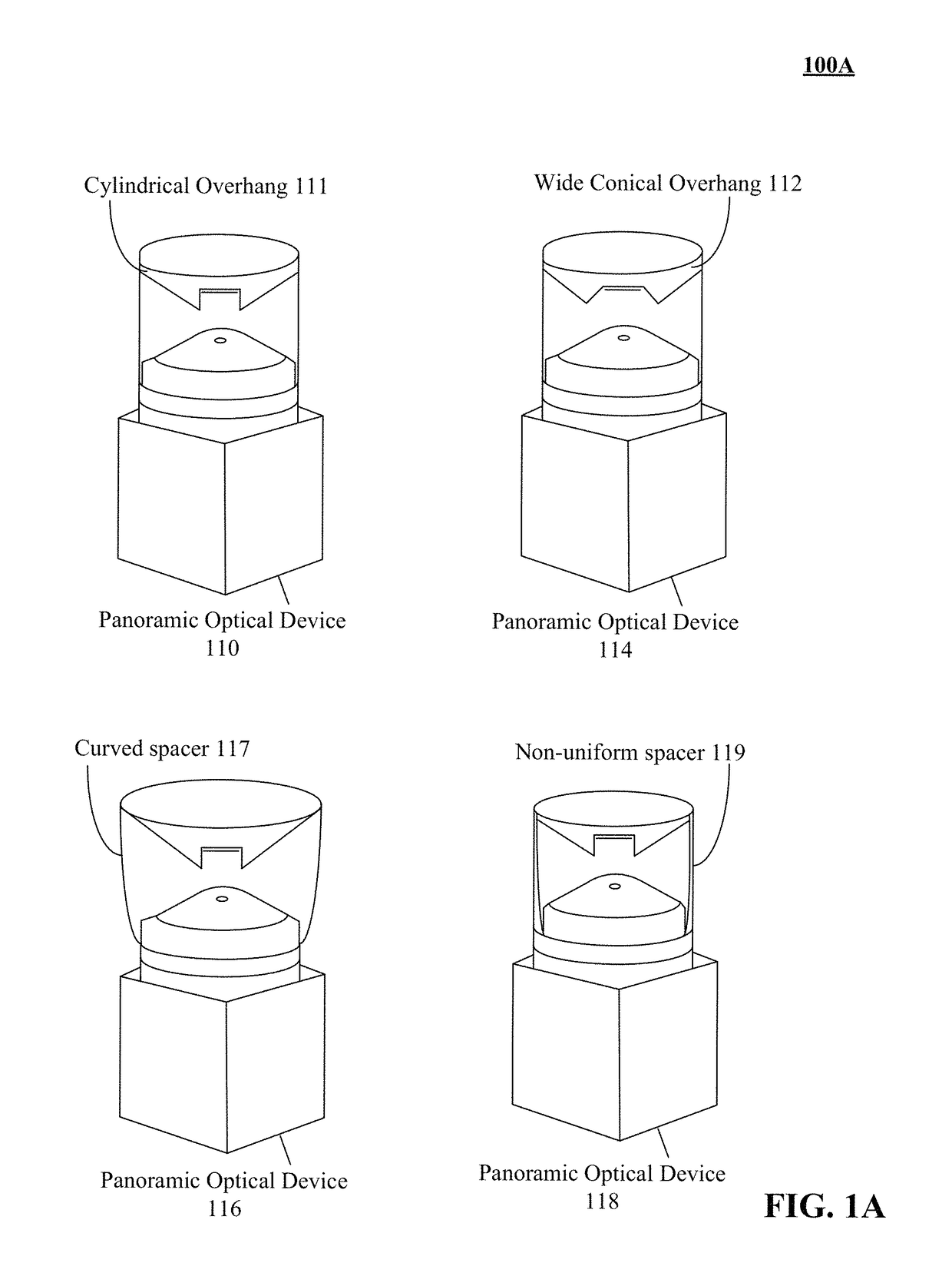
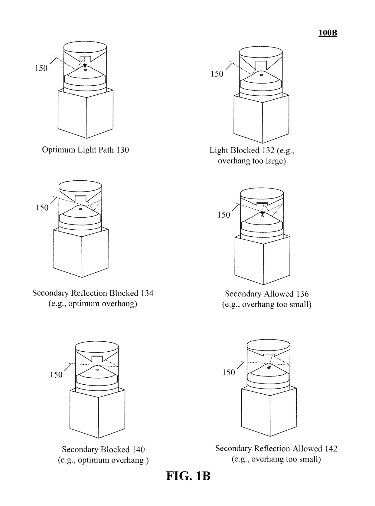
[0005]One aspect of the present invention describes a one-shot panoramic camera optical component including a mirror, an overhang enclosure, and a transparent outer casing. The mirror is positioned within the overhang enclosure of the device in a plane approximately parallel to a circular cross section of a quadric reflector. The mirror reflects environmental light that is reflected by the quadric reflector into an aperture of the quadric reflector. The overhang enclosure has an outer surface that comprises a light absorbing material which absorbs stray light. Stray light is light reflected from an interior of a transparent outer casing. The outer surface absorbs a significant portion of light reflecting off an interior of the transparent outer casing. The transparent outer casing has a circular cross section. A topmost portion of the overhang enclosure is secured to a topmost portion of the transparent outer casing. A bottommost portion of the transparent outer casing is securable to a structure that supports the quadric reflector. An interior volume of the transparent outer casing when secured to the structure includes the quadric reflector, the mirror, and the overhang enclosure. The substantially conical shape of the overhang enclosure permits environmental light to reflect off the quadric reflector without operational blockage while the substantially conical shape absorbs reflections off an interior of the transparent outer casing to prevent secondary reflections from entering the aperture.
[0006]One aspect of the present invention describes a device having a base and a screwable top. The base comprising of a housing that includes a quadric reflector and a set of one or more optical elements. The quadric reflector has an approximately conical shape, which tapers from a wide base to an apex. The apex includes an aperture. The set of one or more optical elements are positioned at least partially within a volumetric region of the quadric reflector. The optical elements focusing light passing through the aperture. The screwable top includes a mirror, and overhang enclosure, and a transparent outer casing. The mirror is positioned within an overhang enclosure of the device in a plane approximately parallel to a circular cross section of a quadric reflector when the screwable top is secured to the base. The mirror reflects environmental light that is reflected by the quadric reflector into an aperture of the quadric reflector. The overhang enclosure has an outer surface that comprises a light absorbing material which absorbs stray light. Stray light is light reflected from an interior of a transparent outer casing. The outer surface absorbs a significant portion of light reflecting off an interior of the transparent outer casing. The transparent outer casing has a circular cross section. An interior volume of the transparent outer casing when secured to the base includes the quadric reflector, the mirror, and the overhang enclosure. The substantially conical shape of the overhang enclosure permits environmental light to reflect off the quadric reflector without operational blockage while the substantially conical shape absorbs reflections off an interior of the transparent outer casing to prevent secondary reflections from entering the aperture.

Problems solved by technology

Providing high quality optics in a panoramic camera is challenging.
However, software correction distortion correction can be limited.
Further, distortion caused from too much light reaching an image sensor cannot be easily corrected through software correction.
The limitation can include image banding which can occur when an environment includes objects such as mirrors and windows which can reflect additional light to optical components.
In these instances, software correction cannot be utilized (or is inefficient / non-optimal) and a new approach as detailed herein significantly improves image capture.
The filtered wavelengths can blur the image and produce color rendering errors in some embodiments.
For example, infrared, violet, and / or ultraviolet wavelengths may be undesired in that they contribute to blurring the image and producing color rendering errors in some embodiments of the disclosure.
Conventional implementations for one-shot cameras have banding issues caused by the reflections that are absorbed by the substantially conical overhang disclosed herein.

Method used


Image

  • Overhang enclosure of a panoramic optical device to eliminate double reflection
  • Overhang enclosure of a panoramic optical device to eliminate double reflection
  • Overhang enclosure of a panoramic optical device to eliminate double reflection

Examples


embodiment 510

[0065]In embodiment 510, an overhang enclosure 512 can be friction fitted to a base of a panoramic optical device. In the embodiment, a bottom portion of a transparent spacer can be securely fitted against a protruding wall of base 514. For example, enclosure 512 can be mated against a lip (e.g., area 516) of base 514. It should be appreciated that enclosure 512 can be fitted to base 514 using one or more traditional and / or proprietary attachment mechanisms. Attachment mechanisms can include, but is not limited to, snapping / locking mechanism, a screw based attachment mechanism, and the like.

embodiment 540

[0066]In embodiment 540, the overhang enclosure 512 can include a conical cross section (e.g., concavity 570) corresponding to dimensions 522, 550 and an overhang 544 with dimension 557 at an angle 556. In one instance, mirror 542 can be recessed within the concavity 570 based on optimum depth 560. In one configuration of the instance, depth 560 can include a cylindrical portion which can recess the mirror 542 for optimum light reflection into aperture of reflector 520. The concavity 570 can be defined by internal angle 554 which can be utilized to control environmental light absorption. That is, angle 554 can be adjusted to ensure optimum light absorption without affecting light reflected from mirror 542 or reflector 520.

[0067]In one instance, overhang 544 can be defined by angle 556 and length 557 which can approximately conform to an inverted conical pyramid. In one embodiment, overhang enclosure 512 can be positioned at a distance 558 from quadric reflector 520 to enable appropr...

embodiment 580

[0070]FIG. 5B shows a ray diagram for a panoramic optical device in accordance with embodiments of the disclosure. Embodiment 580 illustrates environmental light modeling reflection to establish an optimum overhang enclosure.

[0071]In embodiment 580, modeling environmental light to be reflected into the aperture of the optical device while simultaneously eliminating secondary reflections can enable for an optimum overhang enclosure configuration to be determined. For example, light refracted from transparent spacer which travels tangentially across the surface of quadric reflector can be absorbed by an inner wall of an overhang enclosure. It should be appreciated that environmental light which is refracted by transparent spacer onto the mirror in the overhang enclosure can be reflected onto an inner wall of the overhang enclosure. That is, image banding can be eliminated without requiring complex software correction once an optimum enclosure configuration is determined from the light...


PUM


Abstract

A quadric reflector can have an approximately conical shape. The shape can tapers from a wide base to an apex. The apex can include an aperture, a mirror, and a set of one or more optical elements. A mirror can be positioned within an overhang enclosure of the device in a plane approximately parallel to a circular cross section of the conical shape. The mirror can reflect environmental light that is reflected by the quadric reflector into the aperture or reflect light emitting from the aperture onto the quadric reflector. The overhang enclosure can have a substantially conical shape which eliminates secondary reflection resulting from the environmental light reaching the aperture twice. Using the overhang enclosure to absorb the secondary reflection eliminates or minimizes banding.

Description

BACKGROUND[0001]The present invention relates to the field of panoramic optical device and, more particularly, to improving an overhang enclosure of a panoramic optical device to eliminate double reflection.[0002]Providing high quality optics in a panoramic camera is challenging. Different approaches have been taken for this problem. One approach is to move a lens and to capture a set of images as the lens moves, which cover a field of view over time. The images from the moved lens are combined to form panoramic scene. Another approach is to form an array of multiple different camera lenses and to combine the image results captured by the array of lenses into a single image. Still another is to utilize an ultra-wide angle lens (e.g., a fish-eye lens) to capture a scene with a wider-than-normal field of view. Yet another is to use a panoramic optical device to create a 360 degree horizontal field of view using a single shot (a discrete point of time using a single lens). This later a...

Claims


Application Information

Patent Timeline
Patent Type & Authority Patents(United States)
IPC IPC(8): G02B13/06G02B17/08G02B19/00G03B37/06F21V7/04G02B5/00H04N5/232
CPCG02B13/06G02B17/08G02B5/003F21V7/041H04N5/23238G02B19/008G03B37/06H04N23/698G02B17/0689
Inventor ABDALA, JULIODURAZO, PATRICIOPETERSON, GARYRIBEIRO, CLAUDIOROBERTSON, JR., WILLIAM H.
Owner HOYOS INTEGRITY CORP
Learn More