Fastener

a technology of fasteners and fasteners, which is applied in the direction of machines/engines, stators, liquid fuel engines, etc., can solve the problems of inability to load segments, the thermal expansion coefficient of the metallic parts of the engine is typically lower, etc., and achieves the effect of simplifying the structural elements

Inactive Publication Date: 2014-01-23
ROLLS ROYCE PLC
View PDF7 Cites 57 Cited by
  • Summary
  • Abstract
  • Description
  • Claims
  • Application Information

AI Technical Summary

Benefits of technology

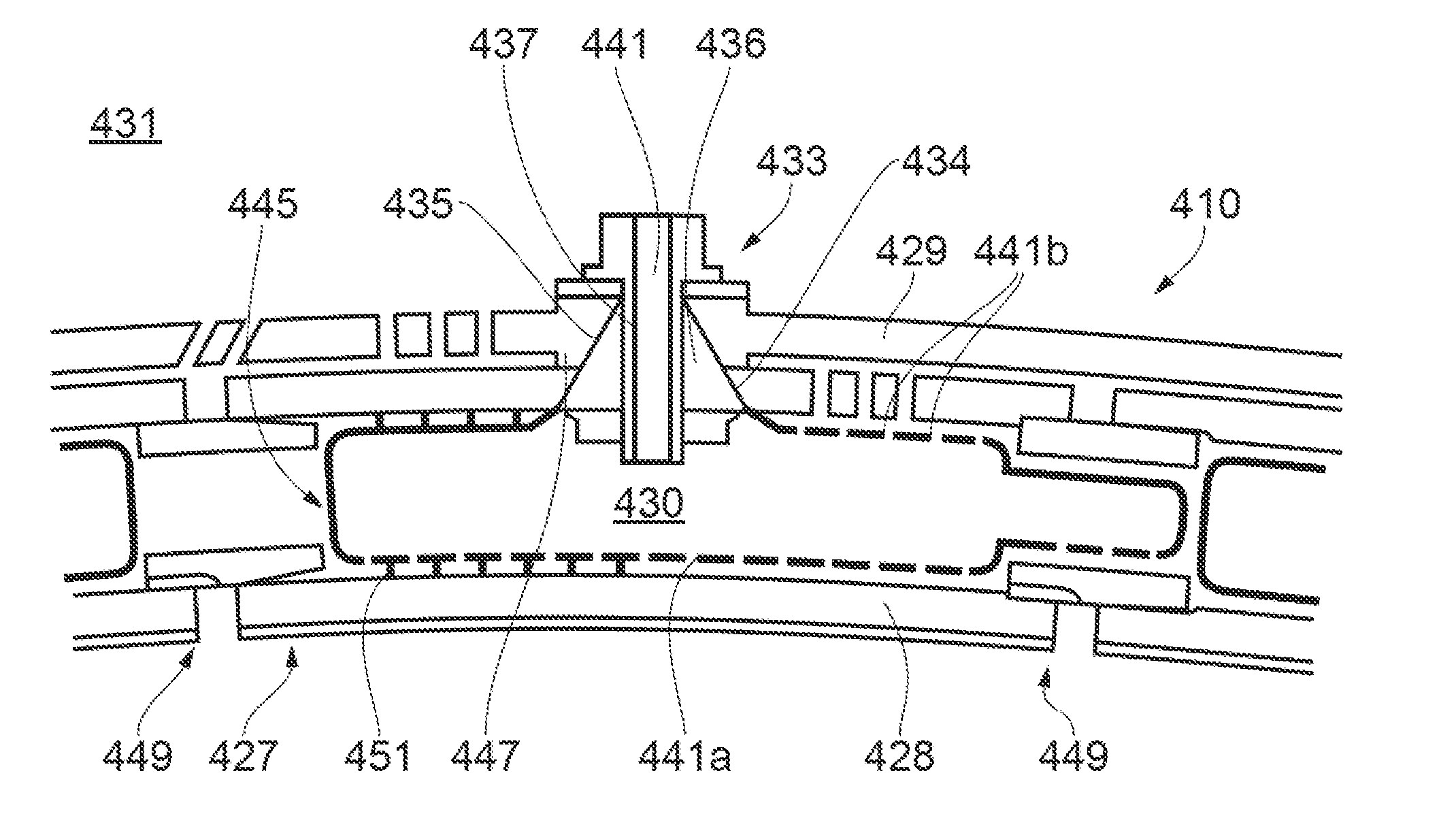
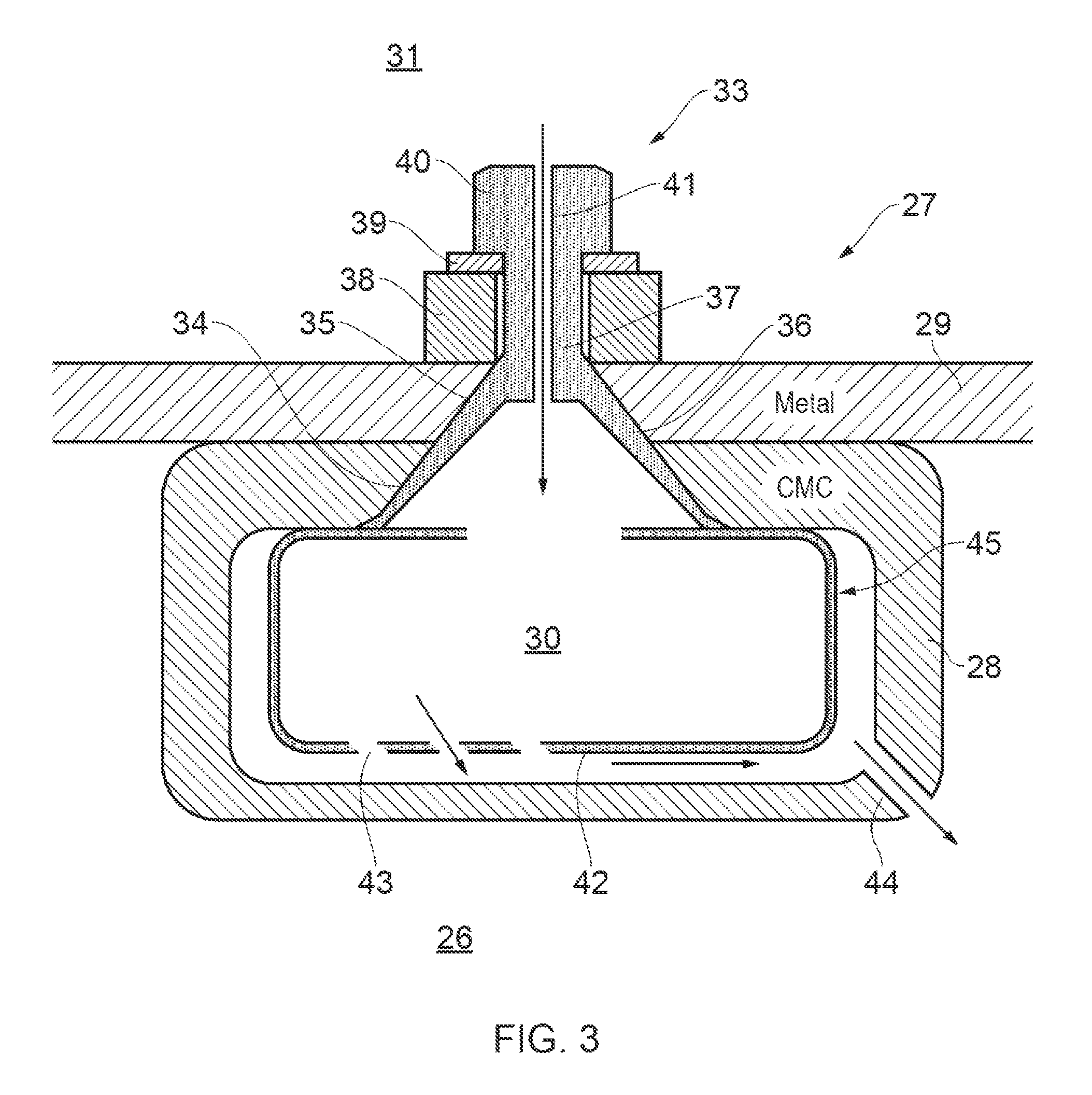
[0013]Thus, advantageously, as well as retaining the connected structural elements together, the functionality of a “daze” fastener can be extended to support fluid communication across the connected structural elements. In this way, separate arrangements for providing such fluid communication (such as, for example, additional aligned apertures in the structural elements) may not be needed, allowing the structural elements to be simplified, and, particularly in relation to ceramic elements, strengthened.
[0015]The fastener may further be adapted to receive connections at either or both ends of the through-hole such that fluid flow can be directed, e.g. by appropriate pipework, away from or to the through-hole. For example, such pipework can help to distribute the fluid flow evenly around the structural elements, and / or can set up a rotational fluid flow.

Problems solved by technology

A difficulty with such ceramic components is their typically lower thermal expansion coefficient relative to the metallic parts of the engine.
Differential thermal mismatches can make fixing of the components to the engine problematic and can lead to unacceptable loadings on the segments.

Method used


Image

  • Fastener
  • Fastener
  • Fastener

Examples


Embodiment Construction

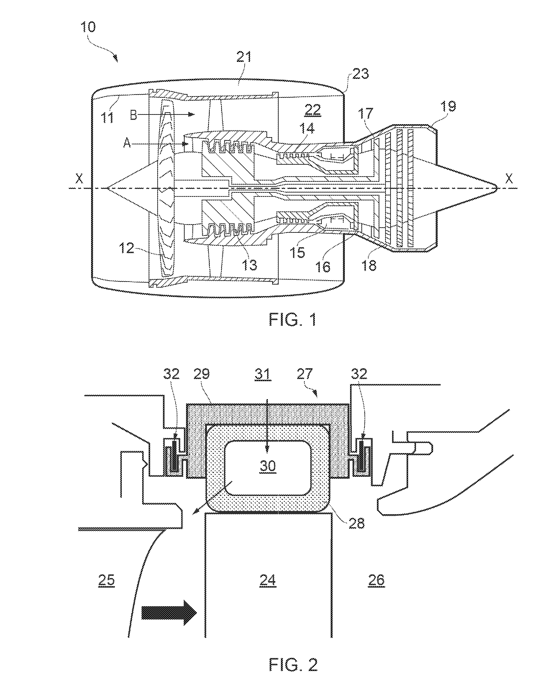
[0041]With reference to FIG. 1, a ducted fan gas turbine engine generally indicated at 10 has a principal and rotational axis X-X. The engine comprises, in axial flow series, an air intake 11, a propulsive fan 12, an intermediate pressure compressor 13, a high-pressure compressor 14, combustion equipment 15. a high-pressure turbine 16, and intermediate pressure turbine 17, a low-pressure turbine 18 and a core engine exhaust nozzle 19. A nacelle 21 generally surrounds the engine 10 and defines the intake 11, a bypass duct 22 and a bypass exhaust nozzle 23.

[0042]The gas turbine engine 10 works in a conventional manner so that air entering the intake 11 is accelerated by the fan 12 to produce two air flows: a first air flow A into the intermediate pressure compressor 13 and a second air flow B which passes through the bypass duct 22 to provide propulsive thrust. The intermediate pressure compressor 13 compresses the air flow A directed into it before delivering that air to the high pre...


PUM

PropertyMeasurementUnit
clamping forceaaaaaaaaaa
homogenousaaaaaaaaaa
metallicaaaaaaaaaa

Abstract

A fastener is provided for connecting two or more structural elements having matching apertures which, when aligned, form a frusto-conical cavity. The fastener includes a body portion having a frusto-conical outer surface which is receivable in the aligned apertures of the structural elements such that the outer surface of the body portion is in mating engagement with the cavity formed by the aligned apertures. The fastener further includes an elongate member which extends from the body portion at the narrow end of the frusto-conical outer surface. The fastener further includes a fixing element carried by the elongate member. The fixing element is operable to exert a clamping force between the frusto-conical outer surface and the fixing element to retain the structural elements in connection therebetween. The fastener further includes a through-hole which extends along the elongate member and which allows fluid communication between opposing sides of the connected structural elements.

Description

FIELD OF THE INVENTION[0001]The present invention relates to a fastener for connecting two or more structural elements, and particularly, but not exclusively, for connecting two or more structural elements which experience differential thermal mismatch.BACKGROUND OF THE INVENTION[0002]The performance of gas turbine engines, whether measured in terms of efficiency or specific output, is improved by increasing the turbine gas temperature. It is therefore desirable to operate the turbines at the highest possible temperatures. For any engine cycle compression ratio or bypass ratio, increasing the turbine entry gas temperature produces more specific thrust (e.g. engine thrust per unit of air mass flow). However, as turbine entry temperatures increase, it is necessary to develop components and materials better able to withstand the increased temperatures.[0003]This has led to the replacement of metallic shroud segments with ceramic matrix composite shroud segments having higher temperatur...

Claims


Application Information

Patent Timeline
Patent Type & Authority Applications(United States)
IPC IPC(8): F01D11/00F16L19/00
CPCF01D11/00F16L19/00F01D11/005F05D2240/11F05D2260/201F05D2260/30F05D2220/32F05D2250/13F05D2300/20F01D11/24F05D2260/36F01D25/246
Inventor HILLIER, STEVEN
Owner ROLLS ROYCE PLC
Why Eureka
Try Eureka