Measurement of the homogeneous temperature of a coil by increasing the resistance of a wire

a technology of resistance and temperature measurement, applied in the direction of transformer/inductance cooling, transformer/inductance with temperature compensation, etc., can solve the problems of high cost and difficult integration of the solution

Active Publication Date: 2017-11-14
SAFRAN ELECTRICAL & POWER
View PDF1 Cites 2 Cited by
  • Summary
  • Abstract
  • Description
  • Claims
  • Application Information

AI Technical Summary

Problems solved by technology

This solution has the first drawback of being expensive since it introduces additional specific equipment, i.e. the temperature probe, which is extraneous to the component to be monitored.
It poses difficulties of integration, since the temperatur

Method used


Image

  • Measurement of the homogeneous temperature of a coil by increasing the resistance of a wire
  • Measurement of the homogeneous temperature of a coil by increasing the resistance of a wire

Examples


Embodiment Construction

[0020]A non-limitative embodiment of the invention is now described in more detail with reference to the accompanying drawings, on which:

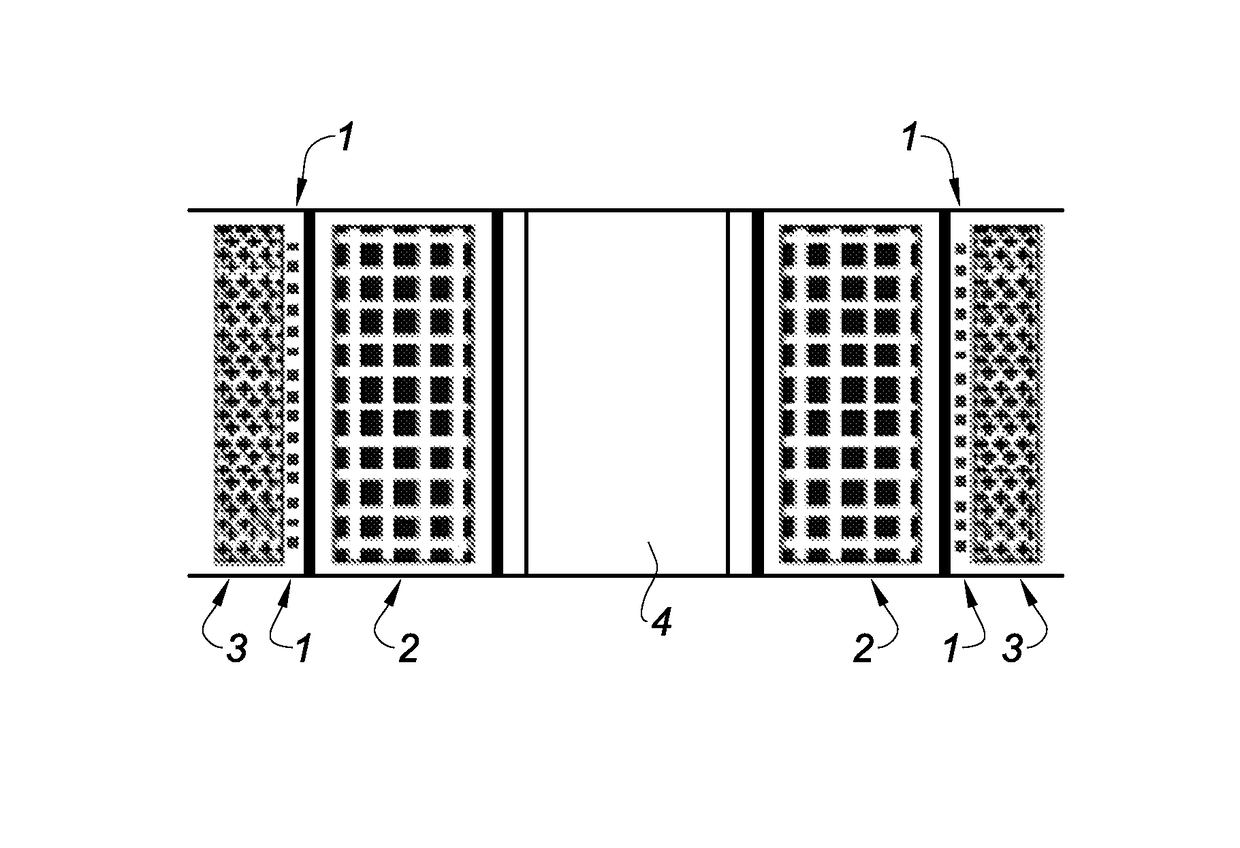
[0021]FIG. 1 is an axial section of a coiled component;

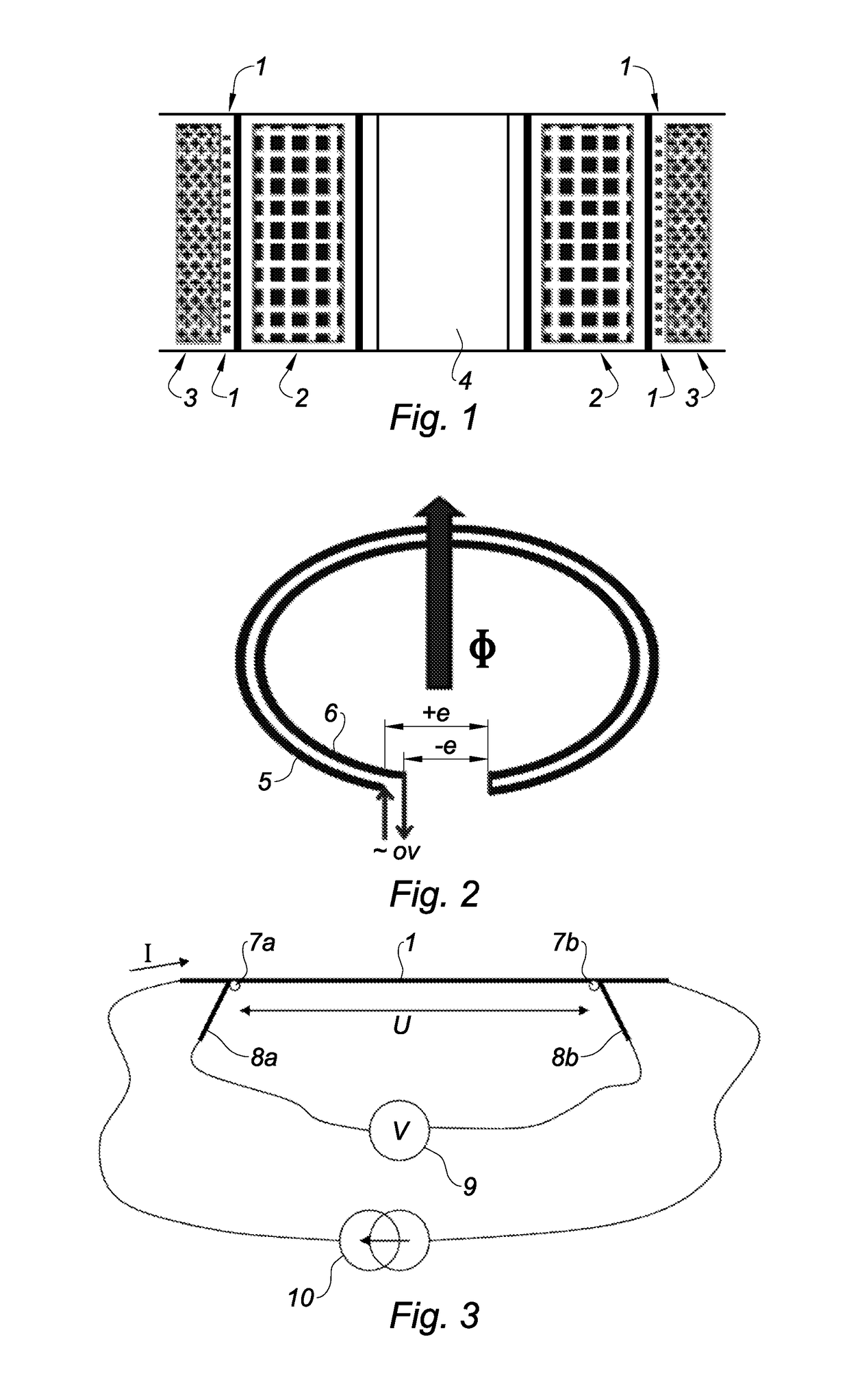
[0022]FIG. 2 is the outline diagram of two turns circulating the measuring current in opposite directions;

[0023]FIG. 3 shows the principle of measuring with four wires on the gauge wire.

[0024]A typical coiled component, for example as transformer as shown in FIG. 1, comprises two active windings 2 and 3. They are configured so that there is an outside winding 3 surrounding the inside winding 2, the whole enveloping a column 4 with a central core.

[0025]The heating of the component is due essentially to the Joule losses in the active windings because of the high currents used. It is a case of estimating the heating of the high-power coiled components, preferably for aeronautical applications. A small-diameter copper gauge wire 1 is therefore wound on a cylinder between the two active windings. Me...


PUM


Abstract

The invention relates to a method of measuring the temperature of a coiled component comprising the injection of a known DC current into a gauge wire (1) made of resistive material, the resistance of the gauge wire varying with temperature according to a known law, the measurement of potential difference between the terminals (7a, 7b) of said gauge wire, and a step of calculation transforming the potential difference into a mean temperature of the gauge wire, said gauge wire (1) being wound inside the coil, and arranged as a series of “outbound” turns (5) and a series of “inbound” turns (6) associated pairwise with a geometry and a position that are substantially equal. It also relates to a component made in order to be able to implement this method and the measurement device as a whole.

Description

TECHNICAL FIELD[0001]The present invention relates to the monitoring of electrical systems installed on an aircraft. It relates more particularly to measuring the temperature of a coiled electrical component.PRIOR ART[0002]A certain number of electronic devices installed on aircraft, in particular computers, are placed in zones where they risk being in contact with a product that is flammable at high temperature, such as engine oil. In this case, for example, the safety rules require that the skin temperature of each casing does not exceed the critical temperature of 204° C., the spontaneous ignition threshold of engine oil.[0003]All passive components that may exceed this temperature must be monitored in order to control this requirement.[0004]With regard more particularly to coiled components, the solution currently used consists of a temperature probe integrated on the outside of the coil that sends an alert message should the critical temperature be exceeded.[0005]This solution ...

Claims


Application Information

Patent Timeline
IPC IPC(8): H01F27/08H01F27/00G01K7/18G01K7/22G01K13/00H01F27/28H01F27/29G01K7/16
CPCG01K7/16G01K7/183G01K7/223H01F27/29H01F27/008H01F27/2823G01K13/00
Inventor PORET, PHILIPPELHOMMEAU, TONY
Owner SAFRAN ELECTRICAL & POWER
Why Eureka
Try Eureka