Radar apparatus and method of determining sign of velocity
a technology of radar apparatus and sign, which is applied in the field of radar apparatus, can solve the problems of high cost of radar apparatus, difficult integration, and difficulty in reducing the cost and size of radar apparatus, and achieves the effect of low cost and high sensitivity
- Summary
- Abstract
- Description
- Claims
- Application Information
AI Technical Summary
Benefits of technology
Problems solved by technology
Method used
Image
Examples
first embodiment
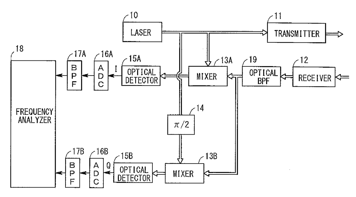
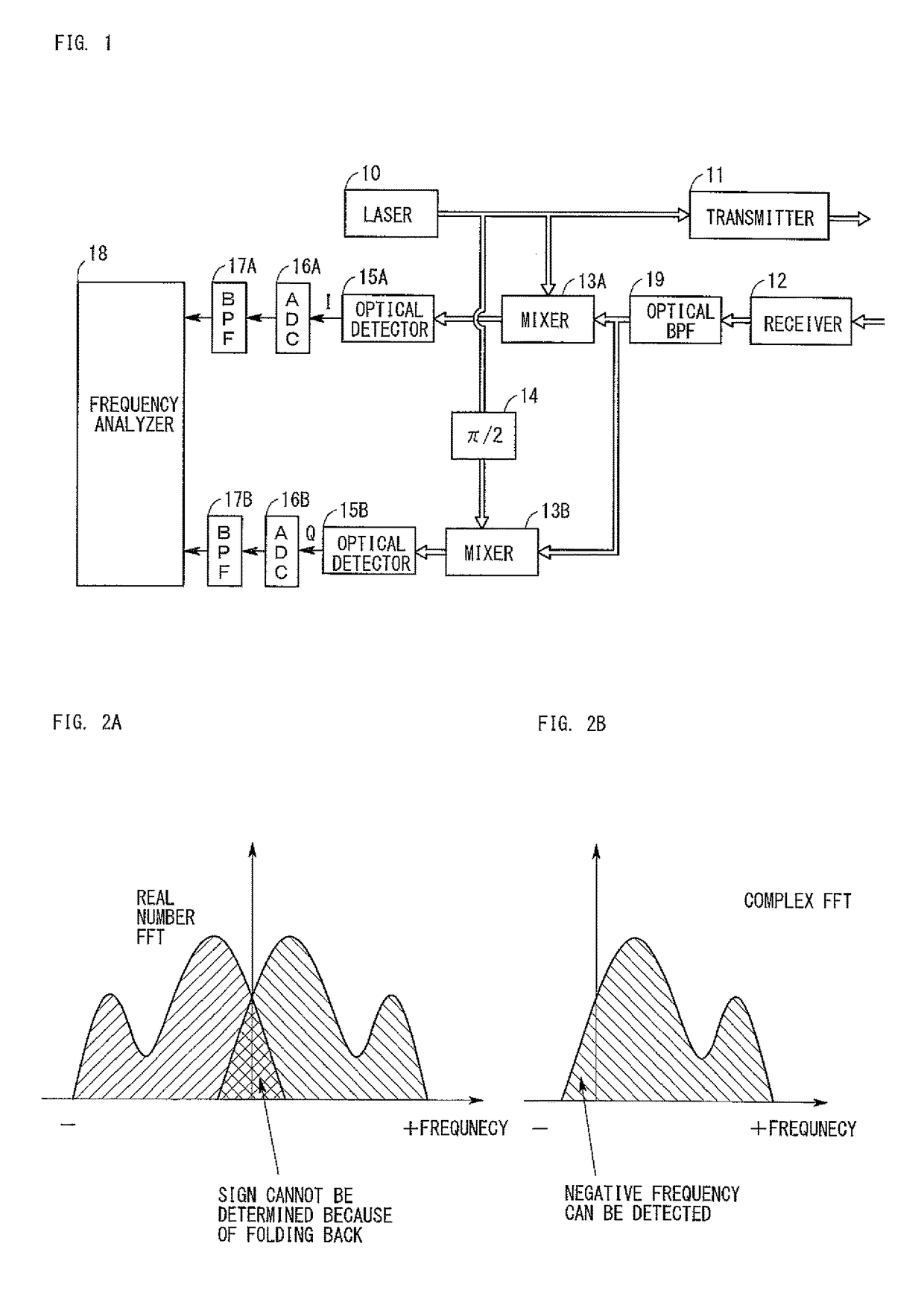
[0026]FIG. 1 is a diagram showing the configuration of a radar apparatus according to a first embodiment. In FIG. 1, arrowed double lines show paths for laser light, and arrowed single lines show paths for electric signals. As shown in FIG. 1, the radar apparatus of the first embodiment is composed of a laser 10, transmitter 11, receiver 12, mixers (couplers, hereinafter the same) 13A and 13B, a π / 2 phase shifter 14, optical detectors 15A and 15B, ADCs (analog-to-digital conversion circuits) 16A and 16B, BPFs (band-pass filters) 17A and 17B, and frequency analyzer 18. Below, these components will be described in detail.
[0027]The laser 10 radiates laser light which is continuous light having a wavelength of 1550 nm. The laser light output from the laser 10 is split into two light beams, one of which is input to a mixer 13A and the other of which is input to the π / 2 phase shifter 14.
[0028]Although the wavelength of the laser light is not limited to 1550 nm, it is desired that the wave...
second embodiment
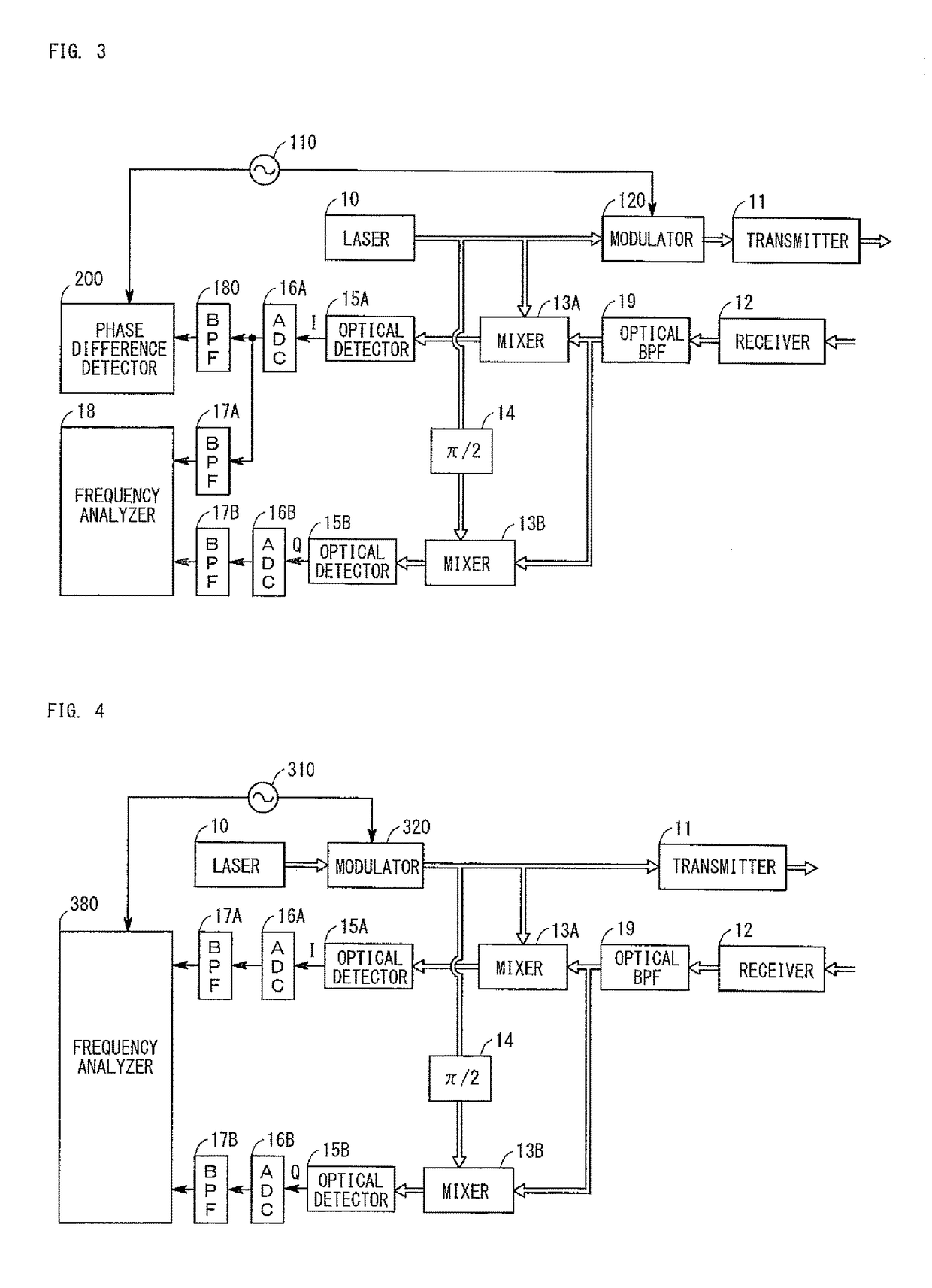
[0046]FIG. 3 is a diagram showing the configuration of a radar apparatus according to a second embodiment. The radar apparatus of the second embodiment is realized by adding the following components to the radar apparatus of the first embodiment.
[0047]As shown in FIG. 3, the radar apparatus of the second embodiment differs from the radar apparatus of the first embodiment in that an oscillator 110, a modulator 120, a BPF 180, and phase difference detector 200 are added so as to measure the distance between the radar apparatus and an object in addition to the velocity of the object. In the below, components different from those of the first embodiment will be described, and operation of the radar apparatus of the second embodiment will be described.
[0048]The oscillator 110 generates a periodic signal which is a cosine wave having a frequency of 100 kHz. This periodic signal is input to the modulator 120 and the phase difference detector 200.
[0049]The periodic signal output from the os...
third embodiment
[0062]FIG. 4 is a diagram showing the configuration of a radar apparatus according to a third embodiment. The radar apparatus of the third embodiment differs from the radar apparatus of the first embodiment in that an oscillator 310 and a modulator 320 are added, and a frequency analyzer 380 is provided in place of the frequency analyzer 18. In the below, components different from those of the first embodiment will be described, and operation of the radar apparatus of the third embodiment will be described.
[0063]The oscillator 310 generates and outputs a triangular wave whose period is T. The modulator 320 frequency-modulates the laser light on the basis of the triangular wave from the oscillator 310, and outputs the modulated laser light. As a result, the frequency of the frequency-modulated laser light changes from the center frequency f0 (1550 nm) by Δf in accordance with the triangular wave whose period is T. The laser light output from the modulator 320 is distributed and is in...
PUM
 Abstract
Description
Claims
Application Information
 - R&D
- Intellectual Property
- Life Sciences
- Materials
- Tech Scout
- Unparalleled Data Quality
- Higher Quality Content
- 60% Fewer Hallucinations
Browse by: Latest US Patents, China's latest patents, Technical Efficacy Thesaurus, Application Domain, Technology Topic, Popular Technical Reports.
© 2025 PatSnap. All rights reserved.Legal|Privacy policy|Modern Slavery Act Transparency Statement|Sitemap|About US| Contact US: help@patsnap.com


