
Inorganic-light-emitter display with integrated black matrix

a technology of black matrix and light-emitting display, which is applied in the field of display, can solve the problems of angular dependence of brightness due to parallax with black matrix in the layer between micro-leds and viewers, and achieve the effect of improving the light output efficiency of the display

Active Publication Date: 2017-11-14
X DISPLAY CO TECH LTD
View PDF181 Cites 67 Cited by
  • Summary
  • Abstract
  • Description
  • Claims
  • Application Information

AI Technical Summary

Benefits of technology

The present invention provides a display with inorganic light emitters distributed over a substrate, and a light-absorbing material formed over the substrate that is in contact with the light emitters. This arrangement results in improved light output efficiency (500% increase) because very little emitted light is absorbed by the light-absorbing material. There is no parallax between the light emitters and the light-absorbing material, and no angular dependence on the light absorption or emission due to the light-absorbing material. Additionally, there is no need for an additional layer for incorporating the light-absorbing material, which reduces emitted light loss and manufacturing steps. The technology also improves angular image quality, increases light-output efficiency, improves contrast, and reduces manufacturing cost.

Problems solved by technology

Furthermore, in a small-aperture-ratio display using micro-LEDs, the problem of angular dependence for brightness due to parallax with a black matrix in a layer between the micro-LEDs and the viewer is particularly acute.

Method used


Image

  • Inorganic-light-emitter display with integrated black matrix
  • Inorganic-light-emitter display with integrated black matrix
  • Inorganic-light-emitter display with integrated black matrix

Examples


Embodiment Construction

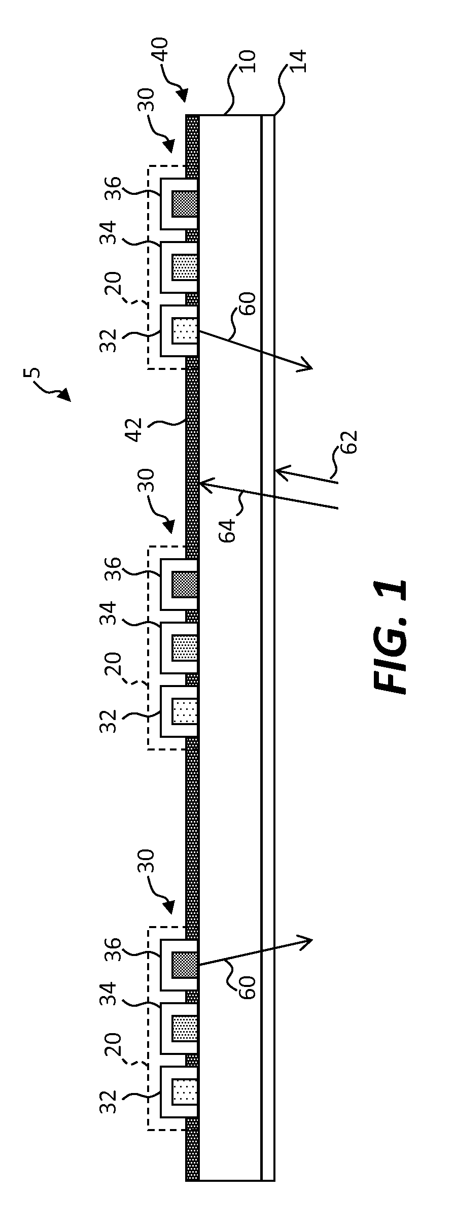
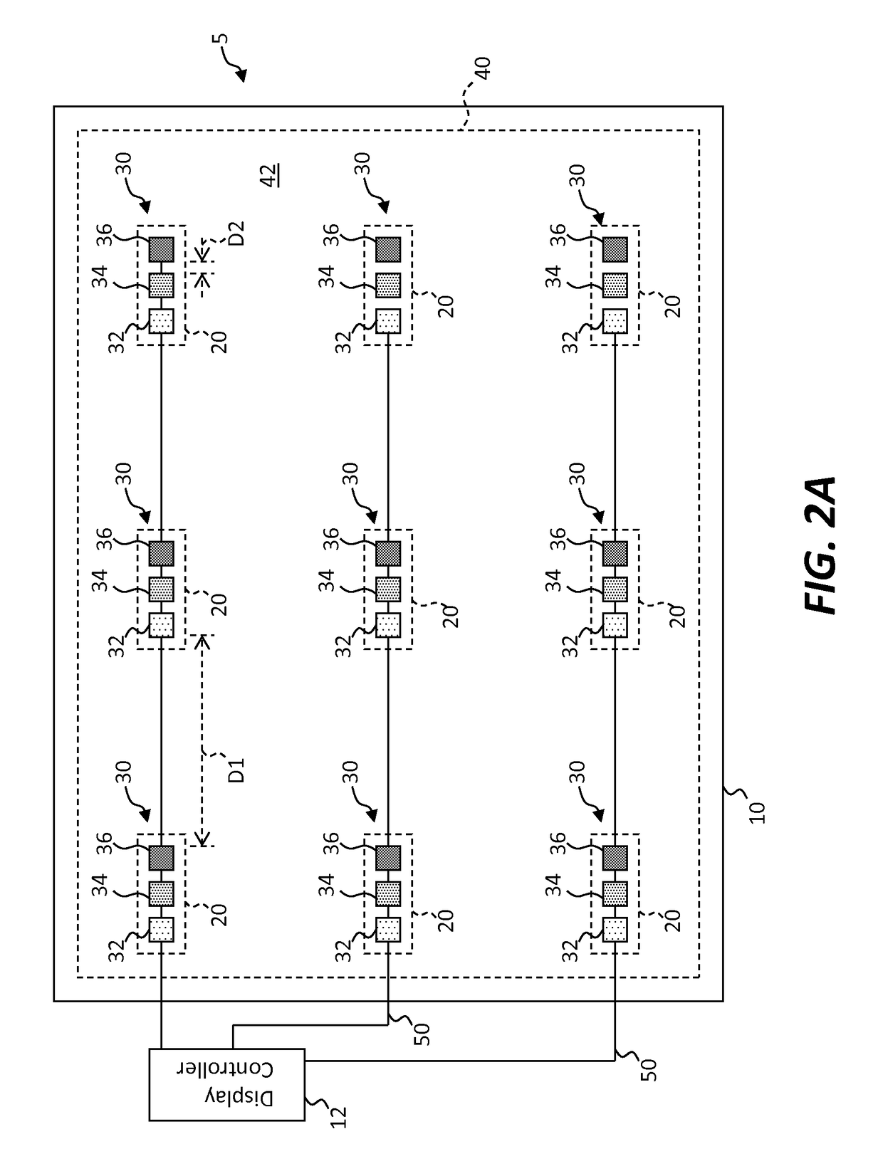
[0276]Referring to the cross section of FIG. 1, the plan view of FIG. 2A, and the perspective of FIG. 2B, where the FIG. 1 cross section is taken along the cross section line A of FIG. 2B, in an embodiment of the present invention an inorganic-light-emitter display 5 includes a display substrate 10. A plurality of spatially separated inorganic light emitters 30 are distributed over the display substrate 10 in a light-emitter layer 40. A light-absorbing material 42 is located over the display substrate 10 in the light-emitter layer 40 and in contact with the inorganic light emitters 30. The light-absorbing material 42 absorbs transmitted ambient light 64 transmitted through the display substrate 10 without interfering with emitted light 60. The light emitters 30 can emit different colors of light, for example red light emitters 32 that emit red light, green light emitters 34 that emit green light, and blue light emitters 36 that emit blue light arranged in a regular array of spatiall...


PUM


Abstract

An inorganic-light-emitter display includes a display substrate and a plurality of spatially separated inorganic light emitters distributed on the display substrate in a light-emitter layer. A light-absorbing layer located on the display substrate in the light-emitter layer is in contact with the inorganic light emitters. Among other things, the disclosed technology provides improved angular image quality by avoiding parallax between the light emitters and the light-absorbing material, increased light-output efficiency by removing the light-absorbing material from the optical path, improved contrast by increasing the light-absorbing area of the display substrate, and a reduced manufacturing cost in a mechanically and environmentally robust structure using micro transfer printing.

Description

PRIORITY APPLICATION[0001]This application claims priority to and the benefit of U.S. Provisional Patent Application No. 62 / 169,520, filed Jun. 1, 2015, titled “Inorganic-Light-Emitter Display with Integrated Black Matrix,” the contents of which are incorporated by reference herein in its entirety.FIELD OF THE INVENTION[0002]The present invention relates to a display including inorganic light emitters and a black matrix for reducing ambient light reflections.BACKGROUND OF THE INVENTION[0003]Flat-panel displays are widely used in conjunction with computing devices, in portable devices, and for entertainment devices such as televisions. Such displays typically employ a plurality of pixels distributed over a display substrate to display images, graphics, or text. For example, liquid crystal displays (LCDs) employ liquid crystals to block or transmit light from a backlight behind the liquid crystals and organic light-emitting diode (OLED) displays rely on passing current through a layer...

Claims


Application Information

Patent Timeline
Patent Type & Authority Patents(United States)
IPC IPC(8): H01L29/18H01L25/065H01L25/16H01L33/44H01L33/58H01L33/62
CPCH01L25/0655H01L25/167H01L33/44H01L2933/0066H01L33/62H01L2933/0025H01L2933/0033H01L33/58H01L2224/96H01L25/0753
Inventor BOWER, CHRISTOPHERDEN BOER, WILLEMMEITL, MATTHEWCOK, RONALD S.
Owner X DISPLAY CO TECH LTD
Learn More