Modular air conditioning system

a technology of module air conditioning and vehicle energy storage, which is applied in the direction of domestic cooling equipment, lighting and heating equipment, heating types, etc., can solve problems such as discomfort from heat, achieve the effects of maximizing maximizing the effectiveness and efficiency of the vehicle's hvac system, and maximizing the fuel economy of the vehicl

Active Publication Date: 2017-11-21
HANON SYST
View PDF19 Cites 6 Cited by
  • Summary
  • Abstract
  • Description
  • Claims
  • Application Information

AI Technical Summary

Benefits of technology

[0008]In accordance and attuned with the present invention a thermal energy storage system of a vehicle and method of operating the same wherein an effectiveness and efficiency of an HVAC system of the vehicle, an effectiveness and efficiency of a WCAC of the vehicle, and a fuel economy of the vehicle are maximized while minimizing complexity and cost has surprisingly been discovered.

Problems solved by technology

The stoppage of the operation of the compressor affects a temperature of the passenger compartment causing thermal discomfort, especially when the ambient temperature is higher.

Method used


Image

  • Modular air conditioning system
  • Modular air conditioning system
  • Modular air conditioning system

Examples


Embodiment Construction

[0017]The following detailed description and appended drawings describe and illustrate various embodiments of the invention. The description and drawings serve to enable one skilled in the art to make and use the invention, and are not intended to limit the scope of the invention in any manner. In respect of the methods disclosed, the steps presented are exemplary in nature, and thus, the order of the steps is not necessary or critical. Except where otherwise expressly indicated, all numerical quantities in this description are to be understood as modified by the word “about” in describing the broadest scope of the technology.

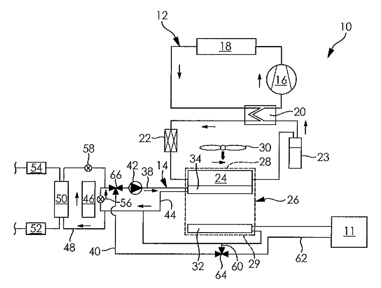
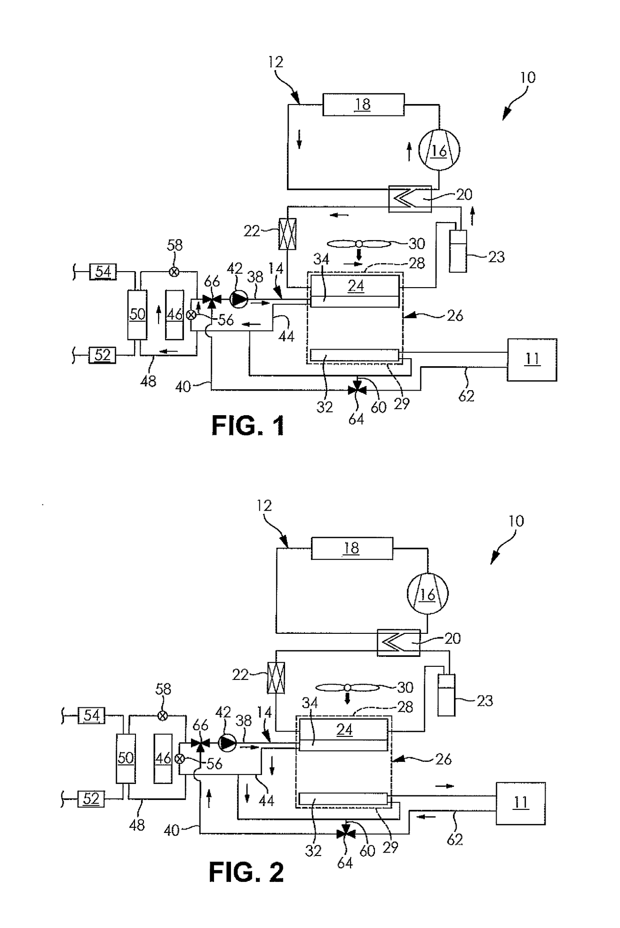
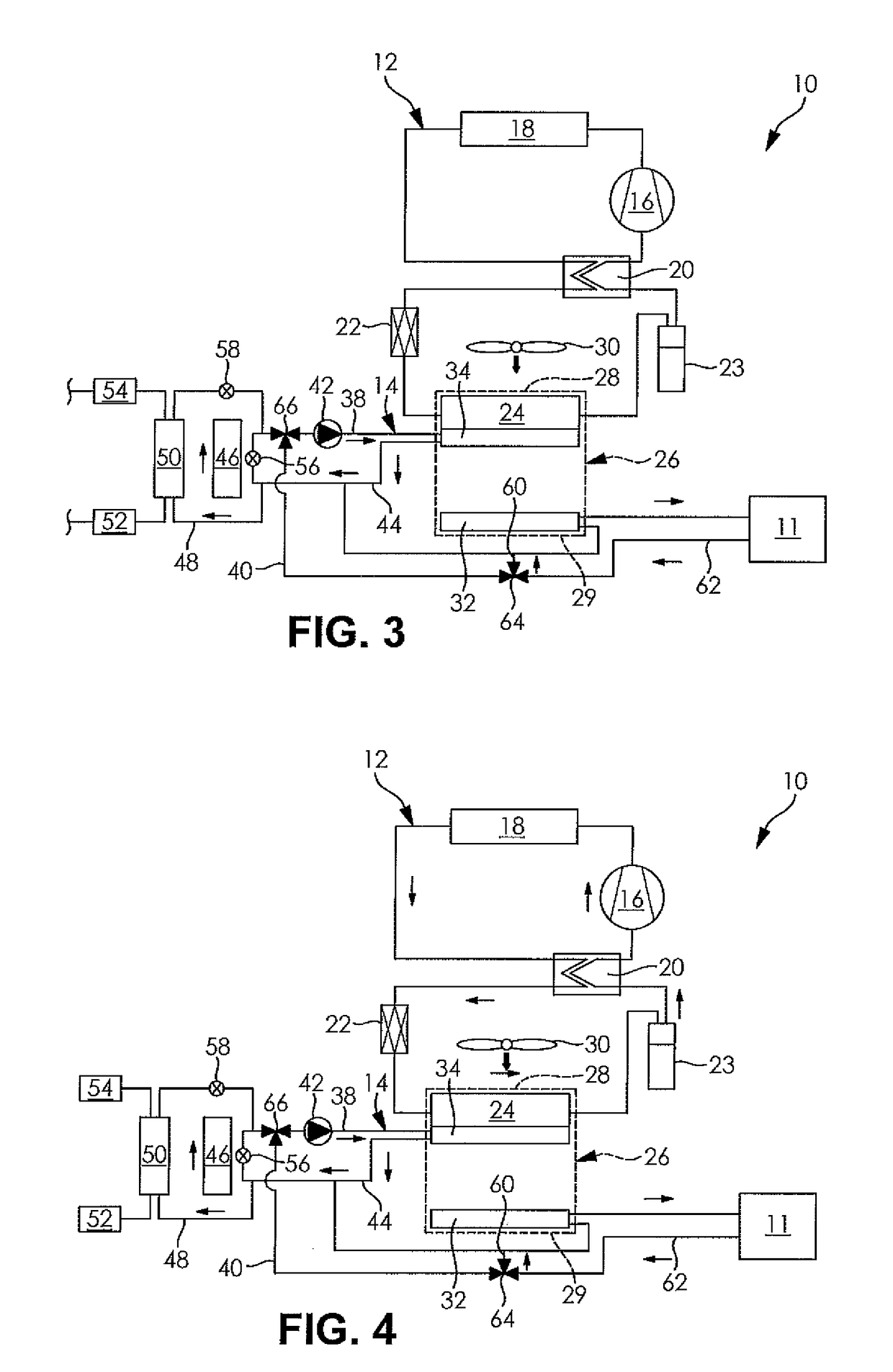
[0018]FIGS. 1-4 illustrate heating, ventilating, and air conditioning (HVAC) thermal energy transfer system 10 of a vehicle according to an embodiment of the disclosure. The vehicle has a fuel powered engine 11 such as an internal combustion engine. The HVAC thermal energy transfer system 10 includes a refrigerant circuit 12 and a coolant circuit 14 of a vehicl...


PUM


Abstract

A thermal energy storage system of a vehicle is disclosed. The thermal energy storage system includes a refrigerant circuit conveying a refrigerant therethrough. The refrigerant circuit includes an evaporator receives a flow of the refrigerant and a flow of air. The thermal energy storage system also includes a coolant circuit conveying a coolant therethrough. The coolant circuit includes a coolant heat exchanger disposed downstream from the evaporator with respect to a direction of the flow of air through the evaporator and an auxiliary heat exchanger receiving a flow of the coolant. The thermal energy storage system further includes a cold storage device in thermal communication with the coolant circuit and a WCAC in fluid communication with the auxiliary heat exchanger.

Description

FIELD OF THE INVENTION[0001]The invention relates to a thermal energy storage system of a vehicle for transferring thermal energy from a refrigerant circuit of an HVAC system of the vehicle to a coolant circuit of the vehicle.BACKGROUND OF THE INVENTION[0002]As commonly known, a vehicle typically includes a climate control system which maintains a temperature within a passenger compartment of the vehicle at a comfortable level by providing heating, cooling, and ventilation. Comfort is maintained in the passenger compartment by an integrated mechanism referred to in the art as a heating, ventilating and air conditioning (HVAC) system. The HVAC system conditions air flowing therethrough and distributes the conditioned air throughout the passenger compartment.[0003]Typically, in operation, a compressor of the HVAC system provides a flow of fluid having a desired temperature to an evaporator disposed in the HVAC system to condition the air. The compressor is generally driven by a fuel-p...

Claims


Application Information

Patent Timeline
Patent Type & Authority Patents(United States)
IPC IPC(8): B60H1/00F24F5/00F25B25/00F25D16/00B60H1/02
CPCB60H1/005F24F5/0017F25B25/005F25D16/00Y02E60/147B60H1/0005B60H1/02F25B25/00Y02E60/14B60H1/00492B60H1/08B60H1/3204B60H1/323F25B39/02F25B49/00F28D20/00Y10S165/904
Inventor GOENKA, LAKHI NANDLAL
Owner HANON SYST
Why Eureka
Try Eureka